EasyManua.ls Logo

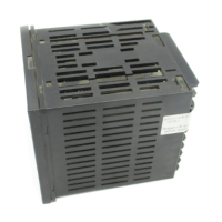
Omron E5AC-T

Omron E5AC-T
438 pages
To Next Page IconTo Next Page
Loading...
At the end of this document you will find links to products related to this catalog. You can go directly to our shop by
clicking HERE. HERE

Table of Contents

Questions and Answers:

Omron E5AC-T Specifications

General IconGeneral
ModelE5AC-T
TypeTemperature Controller
Number of Inputs1
Number of Outputs1
Ambient Operating Temperature0 to 55 °C
Input TypeThermocouple, RTD
Output TypeRelay, Voltage, Current
Control MethodPID Control
Power Supply100 to 240 VAC
Weight200 g
CommunicationRS-485

Summary

Introduction

1-1 Appearance, Features, and Functions of the E5@C-T

Provides an overview of the controller's appearance, features, and main functions.

1-2 IO Configuration and Model Number Legend

Details the controller's I/O configuration and explains the model number legend.

Preparations

2-1 Installation

Covers instructions and considerations for installing the digital temperature controllers.

2-2 Using the Terminals

Explains how to connect and use the controller's various terminals for wiring.

2-4 Using the Setup Tool Port

Details the procedure for connecting and using the setup tool port for configuration.

Part Names and Basic Procedures

3-1 Basic Application Flow

Outlines the fundamental steps and flow for using the digital controller.

3-2 Power ON

Explains the procedure for turning on the digital controller and initial display.

3-3 Part Names, Part Functions, and Setting Levels

Identifies controller parts, their functions, and the various setting levels.

3-4 Procedures after Turning ON the Power Supply

Details the basic steps to follow after the controller is powered on.

Basic Operation

4-1 Moving between Setting Levels

Explains how to navigate through different setting levels of the controller.

4-2 Initial Setup Examples through Starting Program Operation

Provides examples for initial setup and starting program operations.

4-3 Setting the Input Type

Guides users on how to configure the correct input type for the controller's sensor.

4-7 Setting Programs

Explains how to create and set up programs for temperature control.

Advanced Operations

5-1 Shifting Input Values

Describes how to adjust input values for sensor compensation.

5-4 Using Event Inputs

Explains how to utilize event inputs for various control functions.

5-11 Performing Manual Control

Guides users on how to perform manual control operations.

5-13 Using PID Sets

Details how to manage and use multiple PID sets for different control scenarios.

Parameters

6-1 Conventions Used in this Section

Explains conventions and icons used within the Parameters section.

6-3 Operation Level

Describes the operation level for performing control operations and monitoring values.

6-5 Adjustment Level

Provides access to basic controller parameters like PID constants and heating/cooling settings.

6-9 Initial Setting Level

Covers setting basic controller specifications like input type and alarm modes.

User Calibration

7-1 User Calibration

Explains the process and considerations for user calibration of inputs and outputs.

7-3 Thermocouple Calibration

Provides steps for calibrating thermocouple inputs, including group 1 and 2.

7-4 Resistance Thermometer Calibration

Guides on calibrating resistance thermometer inputs using a precision resistance box.

7-5 Calibrating Analog Input

Explains the calibration procedure for current and voltage analog inputs.

7-7 Checking Indication Accuracy

Describes how to verify the controller's indication accuracy after calibration.

Appendices

A-1 Specifications

Lists the detailed specifications and ratings of the digital temperature controllers.

A-4 Error Displays

Explains common error codes and their corresponding meanings and actions.

A-5 Troubleshooting

Offers solutions for common problems encountered during operation.

A-6 Parameter Operation Lists

Provides comprehensive lists of parameters within different setting levels.

A-8 Setting Levels Diagram

Illustrates the navigation path between different setting levels.

A-9 Parameter Flow

Shows the flow and relationships between various parameters.

Index

Related product manuals