Three-phase G3PE
12
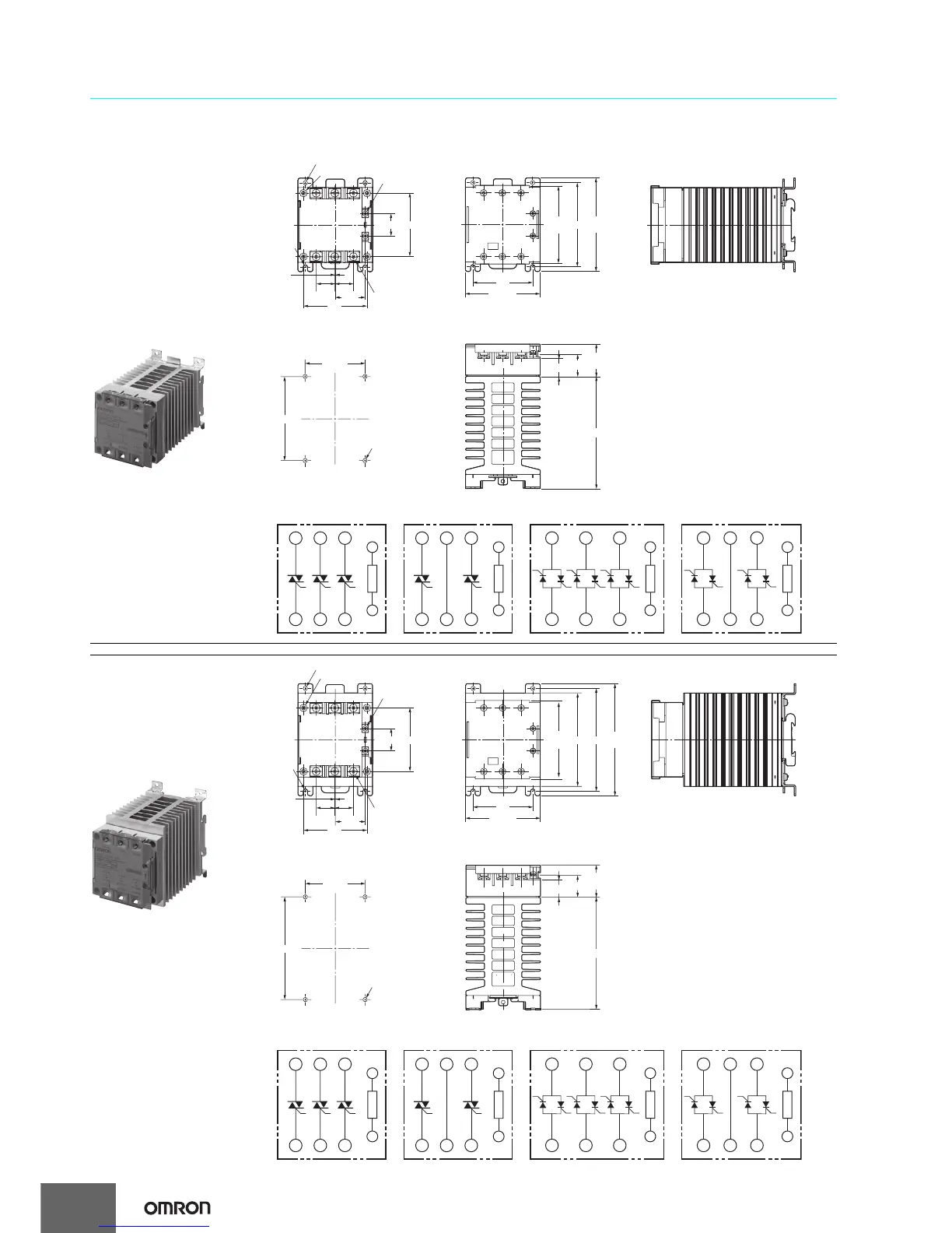
Dimensions
Note: All units are in millimeters unless otherwise indicated.
Solid State Relays
68
68
32.2
20
Six, M4
0.5
20
Two, 4.6-dia. mounting holes
Four, 8 dia.
Two, M3.5
100
max.
84.5
max.
90
64
80 max.
19.1
64
±0.3
90
±0.3
Four, 4.5 dia. or M4
23.2
120 max.
35
max.
24
Two, R2.3
mounting
holes
A1
A2
Input circuit
Input circuit
Input circuit
Input circuit
A1
A2
Terminal Arrangement/Internal Circuit Diagram
G3PE-2@5B-2N
G3PE-215B-3N
L1/R
T1/U T2/V T3/W
L2/S L3/T
L1/R
T1/U T2/V T3/W
L2/S L3/T
L1/R
T1/U T2/V T3/W
L2/S L3/T
A1
A2
(+)
(−)
(+)
(−)
(+)
(−)
(+)
(−)
G3PE-5@5B-2N
L1/R
T1/U T2/V T3/W
L2/S L3/T
A1
A2
G3PE-515E-3N
Note: Without terminal cover. Note: With terminal cover.
Mounting Holes
Models with
DIN Track Mounting
G3PE-215B-3N
G3PE-215B-2N
G3PE-225B-2N
G3PE-515B-3N
G3PE-515B-2N
G3PE-525B-2N
120
max.
84.5
max.
110100
64
80 max.
68
68
32.2
20
Six, M5 (35-A type)
Six, M4 (25-A type)
0.5
20
24
19.1
64
±0.3
110
±0.3
23.2
120 max.
35
max.
Two, 4.6-dia. mounting holes
Four, 8 dia.
Two, M3.5
Four, 4.5 dia. or M4
Two, R2.3
mounting
holes
A1
A2
A1
A2
Terminal Arrangement/Internal Circuit Diagram
G3PE-235B-2N
G3PE-225B-3N
L1/R
T1/U T2/V T3/W
L2/S L3/T
L1/R
T1/U T2/V T3/W
L2/S L3/T
L1/R
T1/U T2/V T3/W
L2/S L3/T
A1
A2
G3PE-535B-2N
L1/R
T1/U T2/V T3/W
L2/S L3/T
A1
A2
G3PE-525B-3N
Input circuit
(+)
(−)
Input circuit
(+)
(−)
Input circuit
(+)
(−)
Input circuit
(+)
(−)
Models with
DIN Track Mounting
G3PE-225B-3N
G3PE-235B-2N
G3PE-525B-3N
G3PE-535B-2N
Note: Without terminal cover. Note: With terminal cover.
Mounting Holes