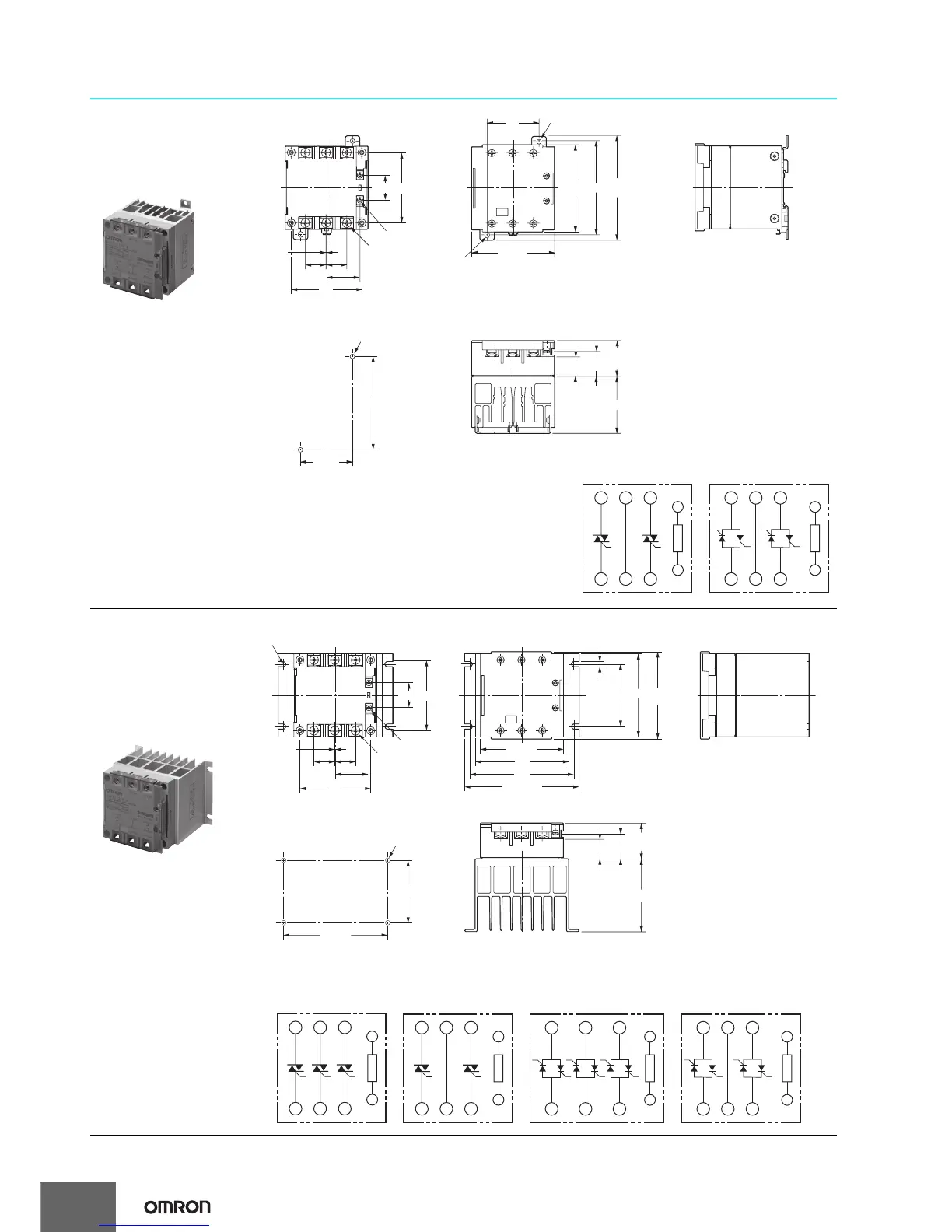
Three-phase G3PE
14
24
68
0.5
20 20
68
32.2
Two, M3.5
Six, M4
90
50
80 max.
84.5
max.
100
max.
4.6 dia.
4.6 × 5.6
elliptical hole
50
±0.3
90
±0.3
Two, 4.5 dia. or M4
Mounting Holes
55 max.
35
max.
23.2
19.1
L1/R
T1/U T2/V T3/W
L2/S L3/T
A1
A2
G3PE-215B-2
L1/R
T1/U T2/V T3/W
L2/S L3/T
A1
A2
G3PE-515B-2
Terminal Arrangement/Internal Circuit Diagram
Input circuit
(+)
(−)
Input circuit
(+)
(−)
DIN Track or screw mounting
Models with Screw Mounting
G3PE-215B-2
G3PE-515B-2
Note: Without terminal cover.
Note: With terminal cover.
A1
A2
A1
A2
G3PE-225B-2
G3PE-215B-3
L1/R
T1/U T2/V T3/W
L2/S L3/T
L1/R
T1/U T2/V T3/W
L2/S L3/T
L1/R
T1/U T2/V T3/W
L2/S L3/T
A1
A2
G3PE-525B-2
L1/R
T1/U T2/V T3/W
L2/S L3/T
A1
A2
G3PE-515B-3
Terminal Arrangement/Internal Circuit Diagram
Input circuit
(+)
(−)
Input circuit
(+)
(−)
Input circuit
(+)
(−)
Input circuit
(+)
(−)
60
80 max.
100
110.5 max.
90
80
84.5
max.
5
24
0.5
20 20
32.2
60
±0.3
100
±0.3
Four, 4.5 dia. or M4
70 max.
35
max.
Four, R2.5
Two, M3.5
Six, M4
Mounting Holes
23.2
19.1
68
68
For screw mounting only
Models with Screw Mounting
G3PE-215B-3
G3PE-225B-2
G3PE-515B-3
G3PE-525B-2
Note: Without terminal cover. Note: With terminal cover.