G7SA
G7SA
134
2.
These times were measured at the rated voltage and an ambient temperature of 23
°
C. Contact bounce time is not included.
3. Pole
3 refers to terminals 31–32 or 33–34, pole 4 refers to terminals 43–44,
pole 5 refers to terminals 53–54, and pole 6 refers to
terminals
63–64.
4.
When using a P7SA Socket, the dielectric strength between coil contacts/dif
ferent poles is 2,500 V
AC, 50/60 Hz for 1 min.
5.
Min. permissible load is for a switching frequency of 300 operations/min.
6. When
operating at a temperature between 70
°
C and 85
°
C, reduce the rated carry current (6 A at 70
°
C or less) by 0.1 A for
each
degree
above 70
°C.
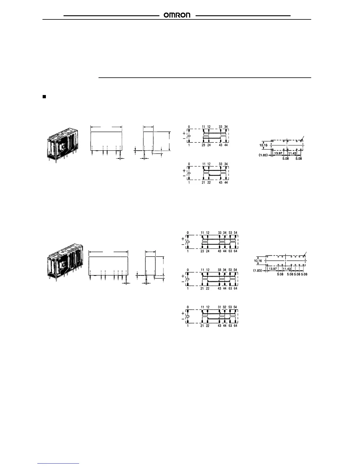
Dimensions
Note:
All units are in millimeters unless otherwise indicated. The diagrams are drawn in perspective.
Safety Relays
G7SA-3A1B
G7SA-2A2B
Terminal
Arrangement/
Internal
Connection Diagram
(Bottom
V
iew)
G7SA-3A1B
G7SA-2A2B
Printed
Circuit
Board
Design
Diagram
(Bottom View)
G7SA-5A1B
G7SA-4A2B
G7SA-3A3B
T
erminal Arrangement/
Internal
Connection
Diagram
(Bottom
V
iew)
G7SA-5A1B
G7SA-4A2B
Printed Circuit Board
Design
Diagram
(Bottom View)
G7SA-3A3B
40
max.
0.5
0.5
3.5
13 max.
24 max.
1
Ten, 1.4 dia.
50 max.
0.5
0.5
3.5
13 max.
24 max.
1
Fourteen, 1.4 dia.
(±0.1 tolerance)
(±0.1 tolerance)
Note: Terminals 23-24, 33-34, and 43-44 are nor-
mally open. Terminals 11-12 and 21-22 are
normally
closed.
Note: Terminals
23-24, 33-34, 53-54, and 63-64
are
normally open. Terminals 11-12, 21-22, and
31-32
are normally closed.