G7SA
G7SA
135
Safety Relay Sockets
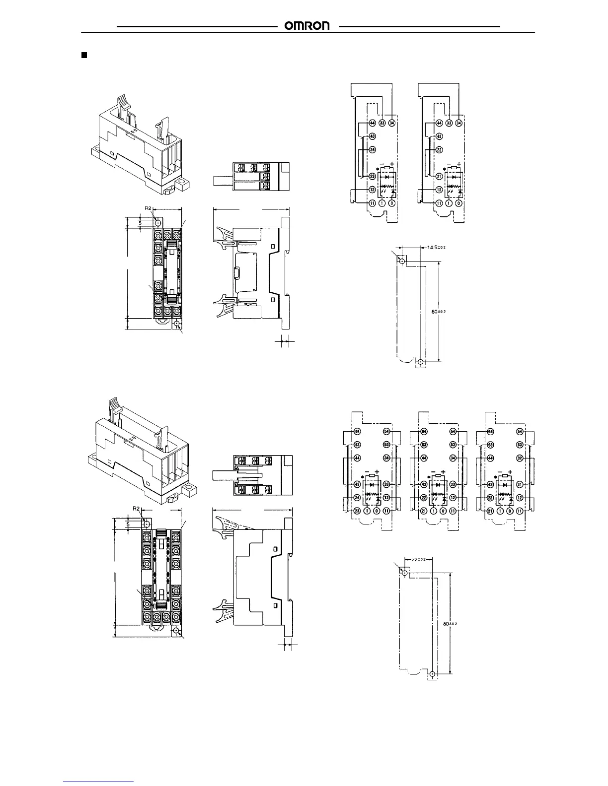
Track-mounting Socket
P7SA-10F, P7SA-10F-ND
Terminal
Installation/Internal Connection Diagram
(T
op V
iew)
G7SA-3A1B
Mounted
G7SA-2A2B
Mounted
Mounting Hole Placement Diagram
(T
op V
iew)
Two, 4 dia. or M3.5
4 dia.
22.5 max.
60.5 max.
9 max.
72 max.
LED
indicator
9 max.
Track-mounting Socket
P7SA-14F, P7SA-14F-ND
Terminal
Arrangement/Internal Connection Diagram
(T
op V
iew)
Mounting Hole Placement Diagram
(T
op V
iew)
G7SA-5A1B
Mounted
G7SA-4A2B
Mounted
G7SA-3A3B
Mounted
4 dia.
30 max. 60.5 max.
9 max.
72 max.
LED
indicator
9 max.
Two, 4 dia. or M3.5
Note: The socket is shown with
the finger cover removed.
Note: The socket is shown with
the finger cover removed.
Note: Only the -ND Sockets have LED indicators.
Note: Only the -ND Sockets have LED indicators.
Ten, M3
Fourteen,
M3
6
6
* This display circuit is
available only for
“-ND” models.
Note: Terminals 23-24,
33-34, and 43-44
are normally
open. Terminals
11-12 and 21-22
are normally
closed.
* This display circuit is
available only for
“-ND” models.
Note: Terminals 23-24,
33-34, 43-44,
53-54, and 63-64
are normally
open. Terminals
11-12, 21-22, and
31-32 are normal-
ly closed.