G7SA
G7SA
136
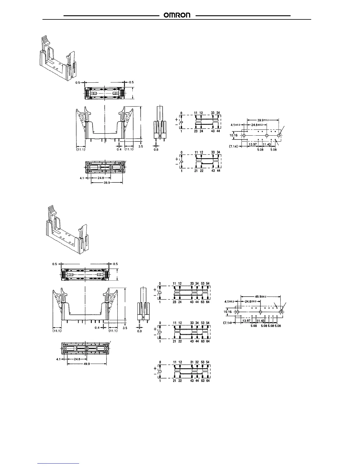
P7SA-10P Back-mounting Socket (for PCB)
Terminal Arrangement/Internal
Connection
Diagram
(Bottom View)
Mounting Hole Placement
(Bottom View)
G7SA-3A1B
Mounted
G7SA-2A2B
Mounted
Three, 3.2 dia.
(for M3 tapping screws)
Three, 2.6 dia.
(for M3 tapping screws)
50 max.
41.5 max.
Ten, 1.1 dia.
15 max.
(±0.1 tolerance)
Note: Terminals
23-24, 33-34, and 43-44 are normally open. T
erminals 1
1-12 and 21-22
are normally closed.
P7SA-14P Back-mounting Socket (for PCB)
Terminal Arrangement/Internal
Connection
Diagram
(Bottom View)
Mounting Hole Placement
(Bottom View)
G7SA-5A1B
Mounted
G7SA-4A2B
Mounted
Three, 2.6 dia.
(for M3 tapping screws)
G7SA-3A3B
Mounted
Three, 3.2 dia.
(for M3 tapping
screws)
60 max.
41.5 max.
15 max.
(±0.1 tolerance)
Fourteen,
1.1 dia.
Note: Terminals
23-24, 33-34, 43-44,
53-54, and 63-64 are normally open. T
erminals 1
1-12, 21-22,
and 31-32 are normally closed.