11
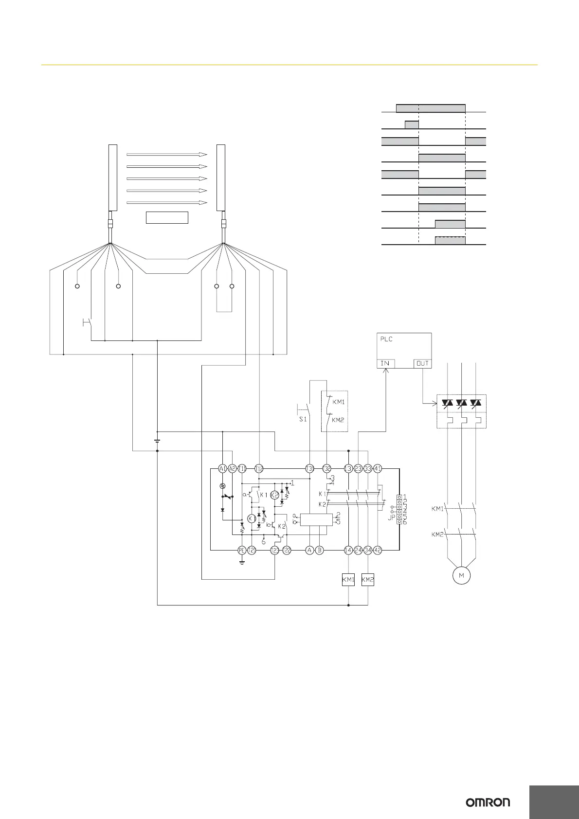
G9SA
G9SA-301 (24 VAC/VDC) with 2-channel Safety Sensor/Manual Reset (PNP models only)
KM3
E1
Feedback loop
Reset switch S1
Timing Chart
PLC input
PLC output
KM3
F3SJ-A Incident
Interrupted
K1 and K2
(NC)
K1 and K2
(NO)
KM1 and KM2
(NC)
KM1 and KM2
(NO)
F3SJ-A: Safety sensor
S1: Reset switch
KM1 and KM2: Magnetic Contactor
KM3: G3J Solid-state Contactor (G3J)
M: 3-phase motor
E1: 24-VDC Power Supply (S82K)
Shield
0V (Blue)
OSSD2 (White)
OSSD1 (Green)
Auxiliary (Yellow)
EDM input (Red)
+24V (Brown)
+24V (Brown)
Open
Interlock selection
input (White)
Reset input (Yellow)
Test input (Green)
Open
(Red)
0V (Blue)
Shield
RS-485(A) (Gray)
*
RS-485(B) (Pink)
Note: This circuit achieves Safety Category 4.
* The F3SJ-A auxiliary output wiring is shown for dark-ON operation.
TH
SA
F3SJ-A
ReceiverEmitter
Control
circuit