G9SA
8
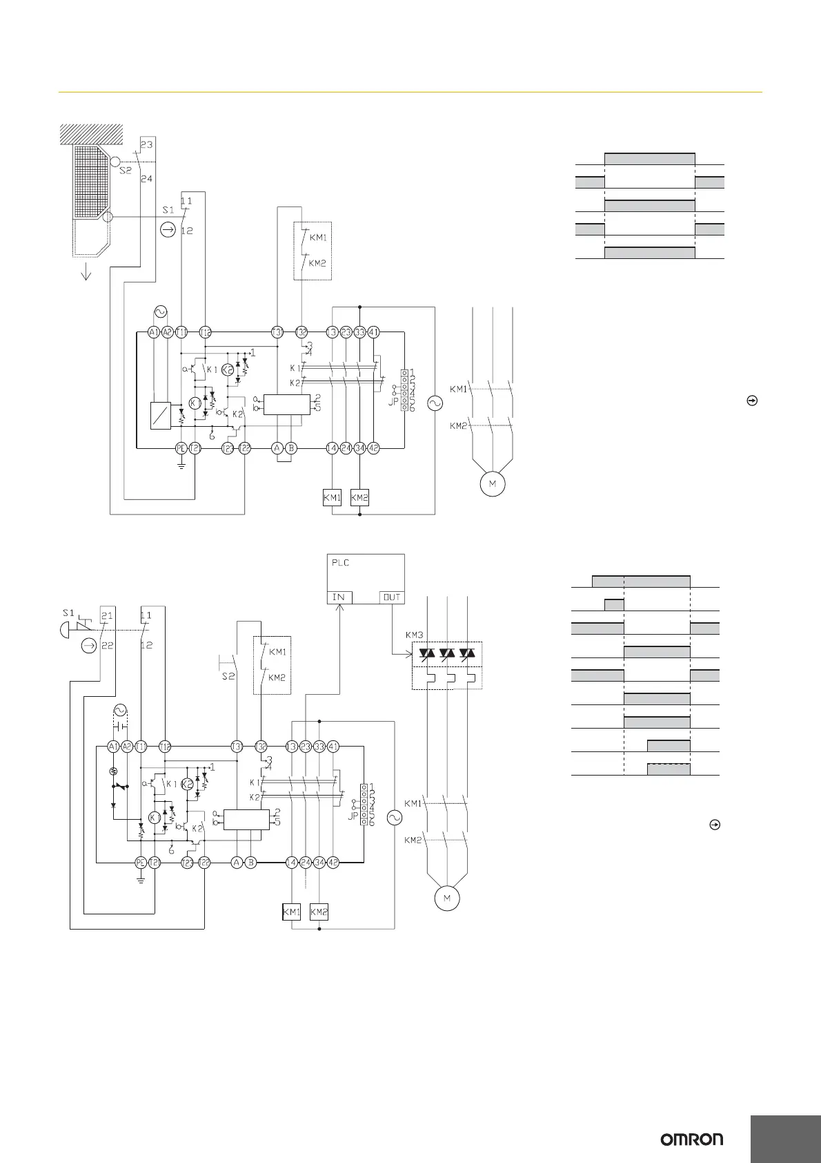
G9SA-301 (100 to 240 VAC) with 2-channel Limit Switch Input/Auto-reset
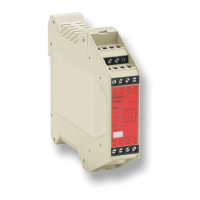
G9SA-301 (24 VAC/VDC) with 2-channel Emergency Stop Switch Input/Manual Reset
Feedback loop
Timing Chart
Open
Limit switches
S1 and S2
K1 and K2
(NC)
K1 and K2
(NO)
KM1 and KM2
(NC)
KM1 and KM2
(NO)
S1: Safety Limit Switch
with direct opening mechanism (NC)
(D4B-N, D4N, D4F)
S2: Limit switch (NO)
KM1 and KM2: Magnetic Contactor
M: 3-phase motor
AC
DC
Note: This circuit achieves Safety Category 4.
Control
circuit
Feedback loop
Timing Chart
PLC input
PLC output
KM3
Emergency
stop switch S1
Reset switch
S2
K1 and K2
(NC)
K1 and K2
(NO)
KM1 and KM2
(NC)
KM1 and KM2
(NO)
S1: Emergency stop switch
with direct opening mechanism
(A165E or A22E)
S2: Reset switch
KM1 and KM2: Magnetic Contactor
KM3: G3J Solid-state Contactor (G3J)
M: 3-phase motor
Note: This circuit achieves Safety Category 4.
Control
circuit
TH
SA