EasyManuals Logo

Omron G9SA User Manual

Omron G9SA
14 pages
To Next Page IconTo Next Page
To Previous Page IconTo Previous Page
Page #9 background imageLoading...
Page #9 background image
9
G9SA
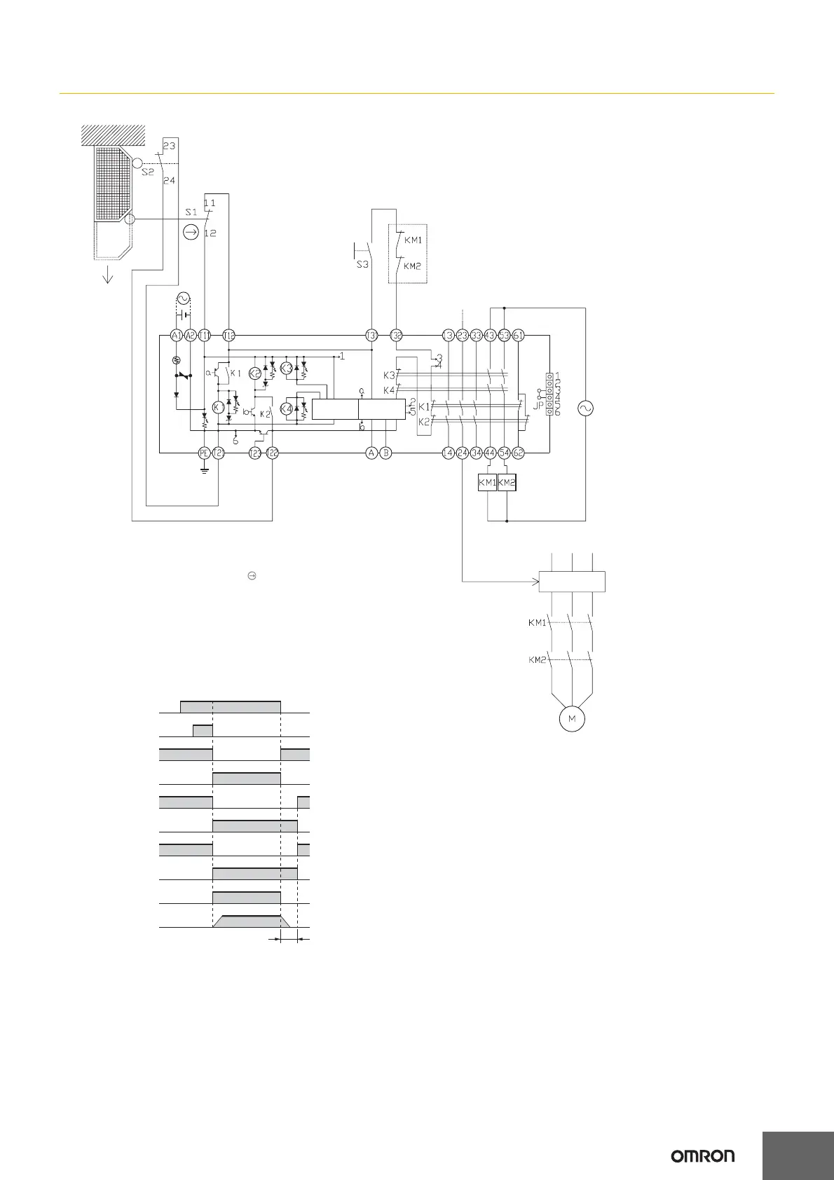
G9SA-321-T@ (24 VAC/VDC) with 2-channel Limit Switch Input/Manual Reset
Feedback loop
Motor controller
Timing Chart
Motor rotation
OFF-delay time
Open
Operation
instruction
S1: Safety Limit Switch
with direct opening mechanism (NC)
(D4B-N, D4N, D4F)
S2: Limit switch (NO)
S3: Reset switch
KM1 and KM2: Magnetic Contactor
M: 3-phase motor
Limit switches
S1 and S2
Reset switch
S3
K1 and K2
(NC)
K1 and K2
(NO)
K3 and K4
(NC)
K3 and K4
(NO)
KM1 and KM2
(NC)
KM1 and KM2
(NO)
Operation
instruction
Note: This circuit achieves Safety Category 4.
The OFF-delay output, however, achieves
Safety Category 3.
Off delay
timer
Control
circuit
TH
SA

Other manuals for Omron G9SA

Questions and Answers:

Question and Answer IconNeed help?

Do you have a question about the Omron G9SA and is the answer not in the manual?

Omron G9SA Specifications

General IconGeneral
Rated Current6A
Mounting TypeDIN Rail
Dimensions90mm x 22.5mm x 100mm
WeightApprox. 200g
Safety CategoryCategory 4
Rated Voltage24 VDC
Operating Temperature-10°C to 55°C
Contact Rating6A at 250V AC
Electrical Life100, 000 operations
Mechanical Life10, 000, 000 operations

Related product manuals