• Please do not connect EtherCAT Junction unit with OMRON position control
unit, Model CJ1W-NC□81/ □82.
EtherCAT Junction Slave
Model GX-JC03/JC06
Instruction Manual
Thank you for purchasing an OMRON EtherCAT Junction slave,
Model GX-JC03/JC06.
To secure safe operation, please be sure to read this manual. Keep this
instruction manual in a safe location and be sure that it is readily available
to your final users of the product.
©OMRON Corporation 2011 All Rights Reserved. 2104233-6B
●
Meanings of Signal Words
● Warning Symbols
Precautions for Safe Use
Precautions for Correct Use
Indicates a potentially hazardous situation which, if not
avoided, could result in death or serious injury.
Additionally, there may be severe property damage.
Warning
Indicates a potentially hazardous situation which, if not
avoided, may result in minor or moderate injury, or
property damage.
Caution
Warning
Do not attempt to disassemble this unit and do not touch the interior
of any Unit while the power is being supplied. In addition, do not turn
on electricity in the state that founded a cover. Doing so may result in
Do not attempt to disassemble, repair, or modify this unit. Any attempt
to do so may result in malfunction, fire, or electric shock.
Take a fail-safe countermeasures by the customer to secure safety in
case of an
abnormal signal casued by broken signal line and
Not doing so may result in serious accidents.
Pay careful attention to the polarities(+/-) when the DC power supply.
A wrong connection may cause malfunction of the system.
• Install correctly according to instructions in the instruction manual. Improper
installation of the Unit may result in malfunction.
• Do not drop any Unit or subject any Unit to excessive shock or vibration.
Otherwise, Unit failure or malfunction may occur.
• Do not operate the control system in the following locations:
• Locations subject to direct sunlight.
• Locations subject to temperatures or humidity outside the range specified in
the specifications.
• Locations subject to condensation as the result of severe changes in
• Locations subject to corrosive or flammable gases.
• Locations subject to dust (especially iron dust) or salts.
• Locations subject to exposure to water, oil, acid, or chemicals.
• Locations subject to shock or vibration.
•
Take appropriate and sufficient countermeasures when installing systems in
the following
locations:
• Locations subject to static electricity or other forms of noise.
• Locations subject to strong electromagnetic fields.
• Locations subject to possible exposure to radioactivity.
• Locations close to power lines.
• Wire all connections correctly according to instructions in the instruction
• Use the correct wiring materials to wire the Units.
• Confirm voltage specifications when wiring communications, the power supply.
Incorrect wiring may result in malfunction.
•
Turn off the power of Controller and all slaves before wiring the communication
•
Take appropriate measures to ensure that the specified power with the rated
voltage and frequency is supplied. Be particularly careful in places where the
power supply is unstable.
An incorrect power supply may result in malfunction.
• Check the user program for proper execution before actually running it on the
Unit. Not checking the program may result in unexpected operation.
• Check all wiring and switch settings to be sure they are correct.
OMRON Corporation
Note: Specifications subject to change without notice.
Caution
•
When transporting this product, use special packing boxes and protect it
from being
to excessive vibration or impact during transportation.
• Mount the Units securely using DIN track.
•
Make sure that the terminal blocks, communications cables, and other items
with locking
devices are properly locked into place. Improper locking may
• Do not extend connection distances or the number of connected nodes
beyond the ranges given in the EtherCAT specifications.
• Do not allow foreign matter to enter this product.
• Always use the specified communications cables and connectors.
• Confirm the polarity of all terminals before wiring them.
•
Always use the power supply voltage specified in the instruction manual. An
incorrect voltage
may result in malfunction or burning.
• Do not bend cables past their natural bending radius or pull on cables.
• Observe the following precautions when wiring the communications cable.
• Separate the communications cables from the power lines or high-tension
• Do not bend the communications cables past their natural bending radius.
• Do not pull on the communications cables.
• Do not place heavy objects on top of the communications cables.
• Always lay communications cable inside ducts.
Emergency stop circuits, interlock circuits, limit circuits, and similar
safe measures
must be externally provided to Slave Unit.
Do not apply the voltage/current outside the specified range to this
product. It may cause a malfunction or fire.
• Be sure to ground when installing the unit.
Notice to Users of EtherCAT Junction Slave in the USA and
Precautions for Complicance with
UL Standatds and CSA Standards
Please use the following installation information instead of the general
information in the instruction manuals in order to use the product under
certified conditions of UL and CSA when the product is installed in the USA or
Canada. These conditions are required by NFPA 70, National Electrical Code
in the USA and the Canadian Electrical Code, Part in Canada and may vary
from information given in the product manuals or safety precautions.
Conformance to EC Directives
•
This product is EMC-compliant when assembled in PLC system . To ensure
the EC Directive conformance of customer’s machinery or equipment in
which the product is incorporated, be sure to observe the following
precautions.
1. This product is defined as an in-panel device and must be installed within
a control panel.
2. Reinforced insulation or double insulation must be used for the DC power
supply connected to the DC power supply unit, communication unit, and
I/O unit.
3. This product complies with the common emission standard (EN61131-2,
EN61000-6-4) with regard to EMI. For the radiated emission requirement
(10-m regulations), in particular, please note that the actual emission
varies depending on the configuration of the control panel to be used, the
connected devices, and wiring methods. Therefore, the customer must
confirm the EC Directive conformance of the overall machinery or
equipment by themselves, even if this EC conforming product is used.
•
This is a class A product. In residential areas it may cause radio
interference, in which case the user maybe required to take adequate
measures to reduce interference.
•
This product is EMC-compliant when the recommend power supply(S8**)
is used
SUI T ABILIT Y FOR USE
OM R O N shall not be res p on s i b le f o r con f o r mity with a n y standa r d s ,
co d e s , or regulat io ns t hat app l y t o t he co m b i n at i o n o f pro d ucts in th e
custome r ’ s a p p licat i on or u s e of the produc t s .
T a k e all n e ces s a r y steps to dete r mine the su i t ability of the pro d uct
f o r the system s , machi ne s , and eq u i p ment with whi c h it will b e us e d .
Please kn o w a n d obse r v e a l l p r ohi b iti o n s of use app l ic a b le to t h e
pro d uct s .
NEVER USE T H E P R ODUC T S FOR AN A P PLIC A T ION IN V O L VING
SERIOUS RISK T O LIFE OR P R OPE R T Y WITHOU T E N SURING
TH A T THE SYSTEM AS A WHOLE HAS BEEN DESIGNED T O
ADDRESS THE RISK S , AND TH A T THE OM R O N P R ODUCTS ARE
P R OPER L Y R A T ED AND INS T ALLED FOR THE INTENDED USE
WITHIN THE O VERAL L E Q UIPMEN T OR SYSTEM .
See al s o pro d u ct catalogs f o r W a r r anty a n d L i mitations of Lia b ilit y .
Fax: (65) 6835-2711
Tel: (65) 6835-3011
Singapore 119967
(Lobby 2), Alexandra Technopark,
No.438A Alexandra Road # 05-05/08
OMRON ASIA PACIFIC PTE.LTD
OMRON ELECTRONICS LLC
Fax: (31) 2356-81-388.
Tel: (31)2356-81-300
The Netherlands
Wegalaan 67-69-2132 JD Hoofddorp
OMRON EUROPE B.V.
Regional Headquarter
Contact: www.ia.omron.com
Tokyo, JAPAN
Industrial Automation Company
One Commerce Drive Schaumburg,
IL 60173-5302 U.S.A
Tel: (1) 847-843-7900
Fax: (1) 847-843-7787
OMRON (CHINA) CO., LTD.
200120, China
Pu Dong New Area, Shanghai,
200 Yin Cheng Zhong Road,
Room 2211, Bank of China Tower,
Fax: (86) 21-5037-2200
Tel: (86) 21-5037-2222
EtherCAT is registered trademark and patented technology, licensed by
Beckhoff Automation GmbH, Germany.
(R)
electric shock.
momentary power interruption.
result in malfunction.
temperature.
• Please pull out the connector inserted in Port 4,5,6 at first when all the ports
of GX-JC06 is used.
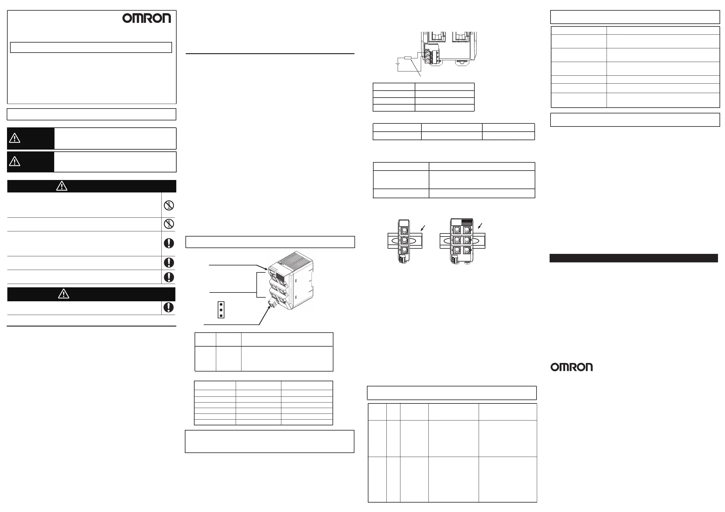
Each Part Name
■
LED
Extinction: Power OFF
Lit: Power ON
Green PWR
L/A Green
Extinction: No connect or No link when
connection
Lit: Link, No data communication
Blinking: Link, Data communication
Indication LED
PWR: Power Supply
LAN Port
3ports: GX-JC03
6ports: GX-JC06
Power Supply Connector
+24V
FG
GND
FK-MCP1.5/3-ST-3.81
L/A LED: Link, ACT
Specification
Power supply Voltage
Consumption
Electric Power
Ambient operating
temperature
Ambient operating
humidity
Storage temperature
Storage humidity
DC 20.4V~28.8V
GX-JC03: 80mA; GX-JC06: 170mA
-10 to 55
°C
-25 to 65
°C
25% to 85% (with no condensation)
25% to 85% (with no condensation)
■
LAN PORT
Name on Tool Name on Unit
1/IN
Detail
2
3
4
5
6
IN
X2
X3
X4
X5
X6
Port1 (IN port)
Port2 (OUT port)
Port3 (OUT port)
Port4 (OUT port)
Port5 (OUT port)
Port6 (OUT port)
Dimension
GX-JC03: 25mm×78mm×90mm;
GX-JC06: 48mm×78mm×90mm
• Fail-safe measures must be taken by the customer to ensure safety in the
event of incorrect, missing, or abnormal signals caused by broken signal
lines, momentary power interruptions, or other causes.
• Default node setting is 0, please set the node by tool.
• Always separate cables by at least 5 mm to prevent unstable operation due to
interference. Do not bundle cables.
Safety Precautions
manual.
• Install external breakers and take other safety measures against
short-circuiting in
external wiring. Insufficient safety measures against
short-circuiting may result in burning.
Canada.
■ Wiring for Unit power connector
The external power supply must be an isolated DC source. It must be equipped
with an over-current protection with current limitation in 4A.
■ Applicable wire size for Unit power source terminal block.
Type
Solid/Strand
Wire size
AWG16-24
Strip lengh
9mm
Do not use ferrule terminals. Insert the strand or solid wire directly into the
holes on the terminal block.
■ Direction for installation
Vertical only
■ Compliance with Class I Division 2 Hazardous Location:
Input and output wiring must be in accordance with Class In Div.2 wiring methods
and in accordance with the authority having jurisdiction.
1. This equipment is suitable for use in Class I, Div.2, Group A, B, C, D or
Non-Hazardous Locations Only.
2. WARNING : Explosion Hazard - Substitution of Components may Impair
Suitability for Class I, Div.2.
3. WARNING : Explosion Hazard - Do not Disconnect Equipment Unless Power
Has Been Switched off or the Area Is Known to Be Non-Hazardous.
4. This device is open-type and is required to be installed in an enclosure suitable
for the environment and can only be accessed with the use of a tool or key.
1. Cet equipement convient a l'utilisation dans des emplacements de Classe I,
Division 2, Groupes A, B, C, D, ou ne convient qu'a l'utilisation dans des endroits
non dangereux.
2. AVERTISSEMENT : Risque d'explosion - La substitution de composants peut
rendre ce materiel inacceptable pour les emplacements de Classe I, Division 2.
3. AVERTISSEMENT : Risque d'explosion - Avant de debrancher l'equipement,
couper le courant ou s'assurer que l'emplacement est designe non dangereux.
4. Ce dispositif est de type ouvert et doit etre installe dans un coffret adapte a
l'environnement et auquel on ne pourra acceder uniquement au moyen d'un
outil ou d'une cle.
+
-
24V DC
Unit Power Supply
Isolated source
Over-current protection (Current limitation: 4A)
Minimum Wire size
24 AWG
Ampere rating of protection
2A
22 AWG
3A
20 AWG 4A
■ LAN Cable
Product name Comment
Twist-pair cable
(Cable with connectors
below are also allowed)
100BASE-TX (Category 5 or higher)
Double-shield (aluminum tape + braided shielding)
RJ45 connector Category 5 or higher Shielded
Troubleshooting
[PWR]
indicator
①Without
power supply,
power supply
disconnection
②Internal power
supply is broken.
Contents
OFF
Power
supply
error
[L/A]
LED
Cause Measures
OFF
OFFON
Without
establishing
Link
①Communication
cable comes off,
disconnection
and short.
②Slave’s hardware
is broken.
③Host master
hasn’t been started
①Check the power
supply unitand
cables.
②Replace the slave.
GX-JC03
DIN Rail
GX-JC06
DIN Rail
①Check the connection
of communication
cable,
Change the
communication cable
② Replace the slave
③ Check status of the
host master.
 Loading...


