EasyManua.ls Logo

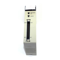
Omron C200H-MC221 User Manual

Omron C200H-MC221
305 pages
To Next Page IconTo Next Page
Page #1 background imageLoading...
Page #1 background image
Cat. No. W315-E1-03
Motion Control Unit
C200H-MC221
OPERATION MANUAL

Table of Contents

Other manuals for Omron C200H-MC221

Questions and Answers:

Omron C200H-MC221 Specifications

General IconGeneral
ModelC200H-MC221
TypeMotion Control Unit
Compatible PLC SeriesC200H
Number of Controlled Axes2
Control MethodPosition Control

Summary

PRECAUTIONS

General Precautions

Outlines general safety and operational guidelines for OMRON products and their application.

Safety Precautions

Details critical warnings about electrical shock and disassembly while power is supplied.

SECTION 1 Components and Switch Settings

Installing the MC Unit

Provides instructions on how to physically mount the MC Unit onto a CPU Backplane safely.

SECTION 2 Wiring

I/O Connector

Details the pin allocation, attachment, and connection examples for the I/O connector.

DRV Connectors

Provides pin allocation, attachment, and connection examples for the DRV X-Y connector for servodrivers.

SECTION 3 Connecting Peripheral Devices

SECTION 4 MC Unit Data

System Parameters

Details the three types of system parameters: unit, memory management, and axis parameters.

Details of Data Transmission and Reception Units

Explains the units used for data transmission and reception, including position data and system parameters.

SECTION 5 G Language

G Functions

Provides detailed descriptions of G functions, including format, parameters, and usage.

SECTION 6 PC Data Area Interface

Allocation of the PC Data Area Interface

Describes the allocation of data areas for C200H/C200HS and C200HX/C200HG/C200HE PC interfaces.

Controlling the MC Unit from the PC

Explains how to control the MC Unit from the PC using ladder programs in manual or automatic mode.

Interface Bits

Lists and explains the bits and flags in the IR area of the PC data area interface.

Interface Bit Specifics

Provides detailed functions of interface bits in the IR area, including timing charts and examples.

SECTION 7 Fixing the Origin

Origin Search Parameters

Details the seven parameters used in the origin search operation, set via MC Support Software.

Setting Up the Absolute Encoder

Describes the purpose and procedure for setting up an absolute encoder connected to the MC Unit.

SECTION 8 Teaching

Setting the Teaching Address

Explains how to set the teaching address in the expansion data area for storing position data.

Performing Teaching

Details the procedure for performing teaching using the Teaching Bit and its associated flags.

SECTION 9 Sample Programs

SECTION 10 Troubleshooting

Error Indicators

Identifies the error indicators on the MC Unit and explains their error processing.

System Errors: Error Codes 0001 to 0017

Lists and describes system errors, their causes, and processing methods, outputting error codes.

Task Errors: Error Codes 0020 to 0045

Details task errors for task 1 and 2, including error codes, causes, and remedies.

Axis Errors: Error Codes 0060 to 0088

Lists and explains axis errors for X and Y axes, providing error codes and processing information.

SECTION 11 Maintenance and Inspection

Appendix D MC Parameter Settings

Machine Parameters

Covers machine-specific parameters like minimum unit, rotation direction, and encoder settings.

Servo Parameters

Covers servo parameters such as error counter warning, position loop gain, and backlash compensation.

Related product manuals