EasyManuals Logo

Omron C200H-MC221 User Manual

Omron C200H-MC221
305 pages
To Next Page IconTo Next Page
To Previous Page IconTo Previous Page
Page #29 background imageLoading...
Page #29 background image
9
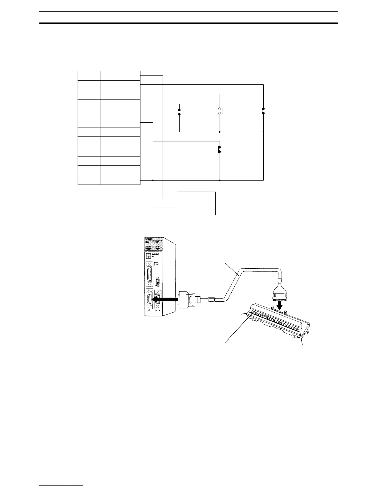
2-1-3 Connection Example
The following diagram shows an example connection for just the X-axis. Corre-
sponding wiring is required for the Y-axis.
I/O connector
CCW limit input Origin proximity
input
CW limit input
Stop input
DC Power
Supply
+24 V
0 V
1 +24V
2 XCWL
3 YCWL
4 XCCWL
5 YCCWL
6 XSTOP
7 YSTOP
8 IN1
9 IN2
10 XORG
11 YORG
14 DC GND
Dedicated Cable and Terminals
XW2Z-100J-F1 MC Unit Cable
XW2B-20J6-6
MC Unit Terminals
XCW, XCCW, origin proximity, and emergency stop
YCW, YCCW, origin proximity, and emergency stop
I/O Connector Section 2-1

Table of Contents

Other manuals for Omron C200H-MC221

Questions and Answers:

Question and Answer IconNeed help?

Do you have a question about the Omron C200H-MC221 and is the answer not in the manual?

Omron C200H-MC221 Specifications

General IconGeneral
BrandOmron
ModelC200H-MC221
CategoryControl Unit
LanguageEnglish

Related product manuals