162
6-5-35 Word n+8 Bit 10: Flash Memory Write Completion Flag
This flag is turned ON when data is written to the flash memory normally.
This flag is used for the timing to turn the Flash Memory Write Bit ON.
This bit will not turn OFF until the Flash Memory Write Bit is turned OFF.
No data can be written when this flag is ON.
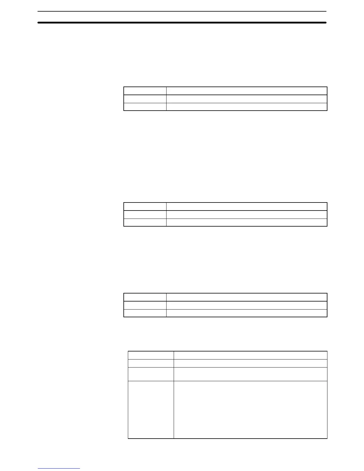
Signal The Flash Memory Write Completion Flag settings have the following meanings.
Signal Function
↑ Data has been written.
↓ No data is being written.
Note Refer to 6-5-13 Word n+1 Bit 13: Flash Memory Write Bit.
6-5-36 Word n+8 Bit 11: Teaching Box Enabled Flag
This flag indicates whether the Teaching Box is in enabled mode. Use this flag as
a condition to interlock the ladder program in this mode.
When this flag is ON, the only commands that can be received from the PC are
Deceleration Stop, Forced Block End, Pause, Optional Input, and M Code
Reset.
Refer to the Teaching Box Operation Manual for more details on the Teaching
Box’s enabled mode.
Signal The Teaching Box Enabled Flag settings have the following meanings.
Signal Meaning
1 ON when the Teaching Box is in enabled mode.
0 OFF when the Teaching Box isn’t in enabled mode.
6-5-37 Word n+8 Bit 12: Teaching Box Protected Flag
This flag indicates whether the Teaching Box is in protect mode. Use this flag as
a condition to interlock the ladder program in this mode.
No operations can be performed from the PC when this flag is ON.
Refer to the Teaching Box Operation Manual for more details on the Teaching
Box’s protect mode.
Signal The Teaching Box Protected Flag settings have the following meanings.
Signal Meaning
1 ON when the Teaching Box is in protect mode.
0 OFF when the Teaching Box isn’t in protect mode.
6-5-38 Word n+8 Bit 13: Initial Setting Alarm Flag
This flag will be turned ON under one of the following conditions.
• The initial setting area is not within the following areas.
PC model Expansion data area
C200H DM 0000 to DM 0899
C200HS DM 0000 to DM 0999
DM 2000 to DM 5999
C200HX,
C200HG, and
C200HE
Model without EM area
DM 0000 to DM 0999
DM 2600 to DM 5999 (The upper limit depends on the
memory size.)
Model with EM area
DM 0000 to DM 0999
DM 2600 to DM 5999 (The upper limit depends on the
memory size.)
EM 0000 to EM 6143
Interface Bit Specifics
Section 6-5
 Loading...


