15
2-2-4 Connection Examples
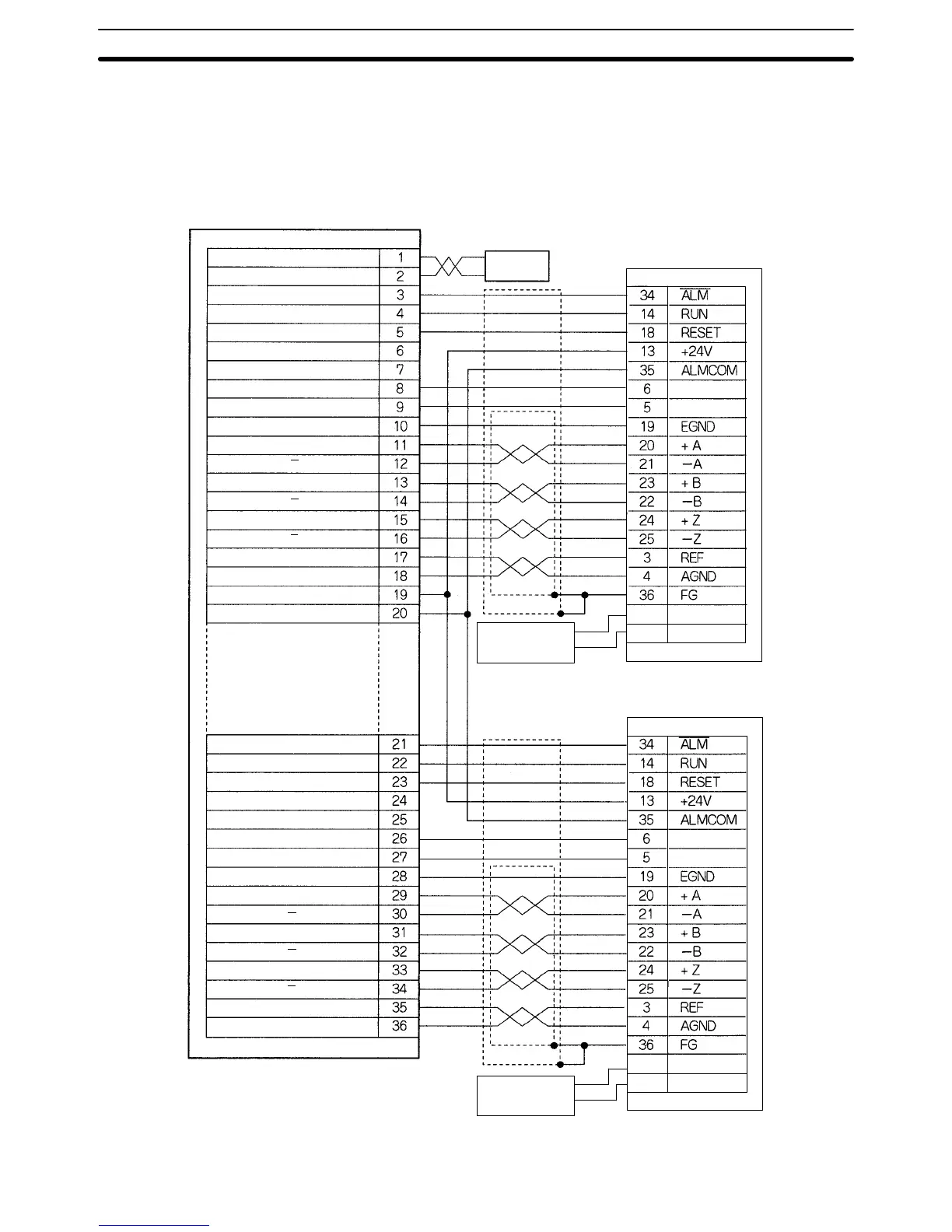
Connection to the U-series (30 to 750 W) Models (Using an Absolute Encoder)
Y-axis alarm input
Y-axis run output
Y-axis alarm reset output
Y-axis feedback ground
Y-axis phase A input
Y-axis phase A
input
Y-axis phase B input
Y-axis phase B
input
Y-axis phase Z input
Y-axis phase Z
input
Y-axis speed control
Y-axis speed control ground
24 VDC input
24 VDC input ground
X-axis alarm input
X-axis run output
X-axis alarm reset output
X-axis SEN signal ground
X-axis feedback ground
X-axis phase A input
X-axis phase A
input
X-axis phase B input
X-axis phase B
input
X-axis phase Z input
X-axis phase Z
input
X-axis speed control
X-axis speed control ground
24 VDC output
24 VDC output ground
Dedicated Driver Cable: R88A-CPU00jM2
DRV X-Y connector
X-axis SEN signal output
AC Servodriver
R88D-UAjjj
Battery
(+2.8 to 4.5 V)
AC Servodriver
R88D-UAjjj
MC Unit
DC Power
Supply
+24 V
0 V
Red
Black
SENGND
SEN
SENGND
SEN
28
29
BAT
BATGND
+
–
Red
Black
CN1
CN1
BATGND
28
BAT
29
Battery
(+2.8 to 4.5 V)
+
–
Red
Blue
Y-axis SEN signal output
Y-axis SEN signal ground
DRV Connectors
Section 2-2
 Loading...


