16
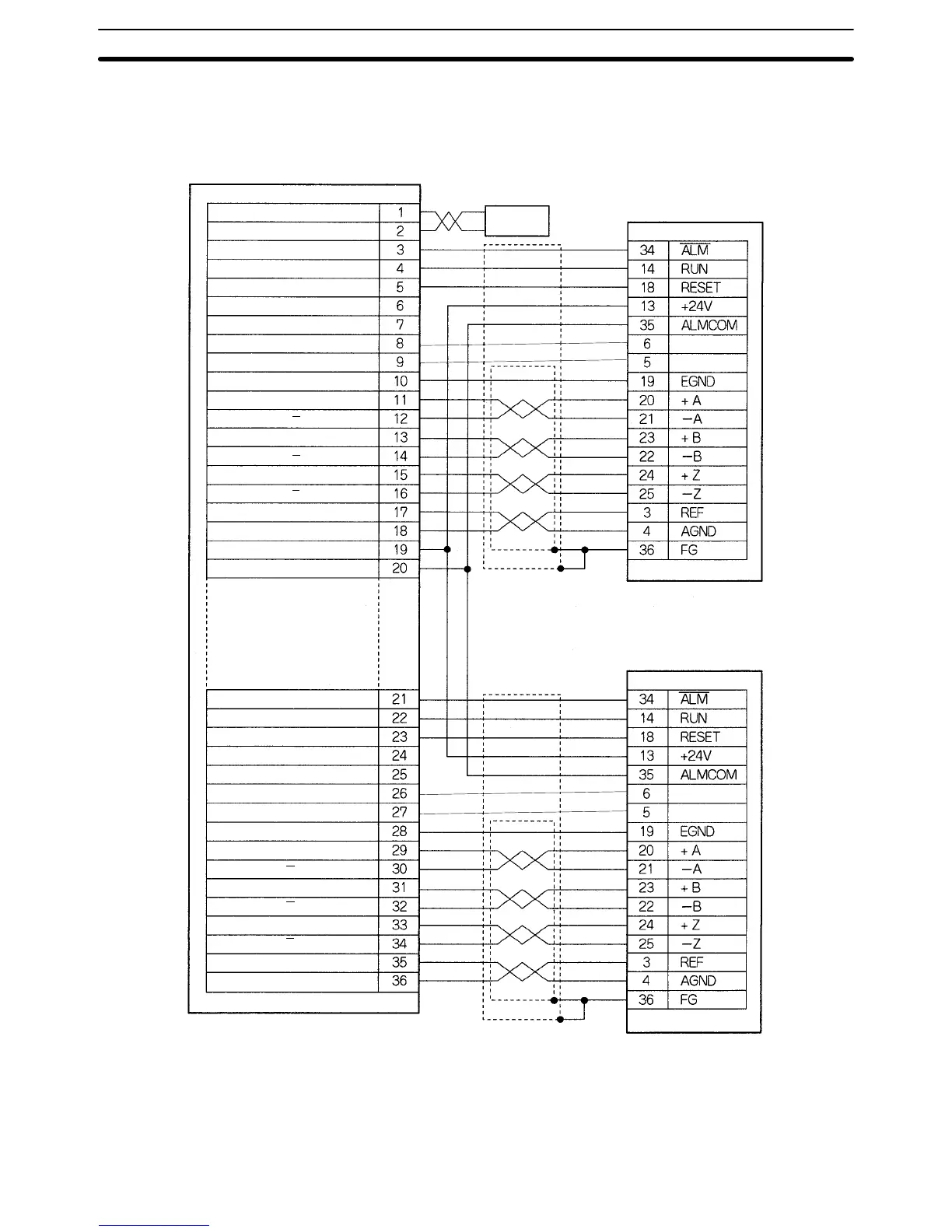
Connection to the U-series (30 to 750 W) Models (Using an Incremental Encoder)
Dedicated Driver Cable: R88A-CPU00jM2
DRV X-Y connector
AC Servodriver
R88D-UAjjj
AC Servodriver
R88D-UAjjj
Y-axis SEN signal ground
Y-axis SEN signal output
MC Unit
24 VDC input
24 VDC input ground
X-axis alarm input
X-axis run output
X-axis alarm reset output
X-axis feedback ground
X-axis phase A input
X-axis phase A
input
X-axis phase B input
X-axis phase B
input
X-axis phase Z input
X-axis phase Z
input
X-axis speed control
X-axis speed control ground
24 VDC output
24 VDC output ground
Y-axis alarm input
Y-axis run output
Y-axis alarm reset output
Y-axis feedback ground
Y-axis phase A input
Y-axis phase A
input
Y-axis phase B input
Y-axis phase B
input
Y-axis phase Z input
Y-axis phase Z
input
Y-axis speed control
Y-axis speed control ground
DC Power
Supply
+24 V
0 V
Red
Black
CN1
CN1
X-axis SEN signal ground
X-axis SEN signal output
Note In the case of the incremental encoder, terminals 5 and 6 on the Servodriver side
are connected. However, this can be ignored. Users are not required to connect
them.
DRV Connectors
Section 2-2
 Loading...


