174
Signal The Error Counter Alarm Flag settings have the following meanings.
Signal Meaning
1 ON when the error counter exceeds the error warn count.
0 OFF when the error counter is less than the error warn count.
6-5-61 Word n+16 Bit 07: Alarm Input (X-axis)
This flag is turned ON when the driver alarm input is ON; it is turned OFF when
the alarm input is OFF. The alarm inputs for the Y axes (bit 07 in words n+19)
operate in the same way.
Signal The Alarm Input settings have the following meanings.
Signal Meaning
1 ON when the driver alarm input is ON.
0 OFF when the driver alarm input is OFF.
Note Refer to 6-5-29 Word n+5 Bit 11: Driver Alarm Reset Bit.
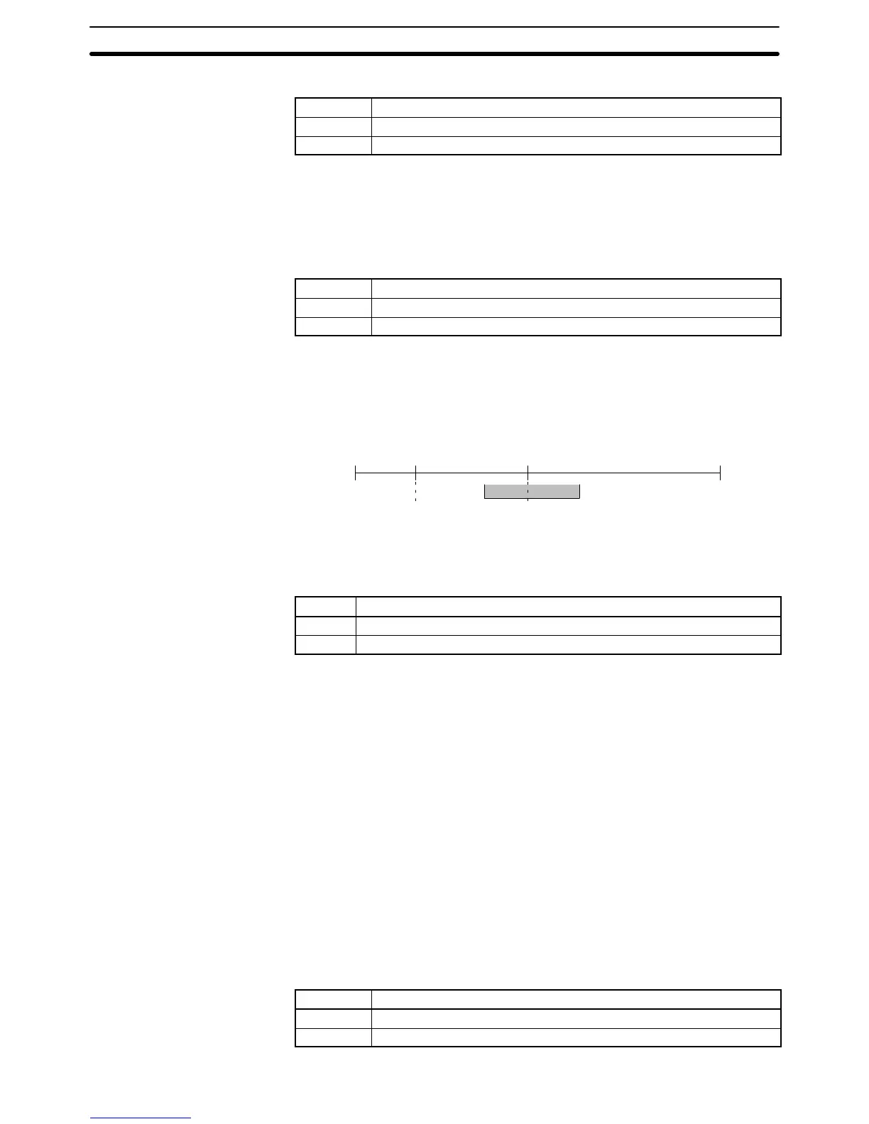
6-5-62 Word n+16 Bits 08 to 15: Zone Flags (X-axis)
Word n+16 bits 08 through 15 are the flags for zones 1 through 8. These flags are
turned ON when the axis is within the zone specified in the zone parameters.
CCW Present value
CW
Present value
Zone Flag OFF Zone Flag ON
Zone setting
The Zone Flags for the Y axes (bits 08 to 15 in word n+19) operate in the same
way.
Signal The Zone Flag settings have the following meanings.
Signal Meaning
1 ON when axis is within the zone’s range.
0 OFF when axis is outside of the zone’s range.
6-5-63 Word n+19 Bit 15: MPG Operation Flag (X-axis)
This flag is used only if Y axis is used for an MPG. (Refer to Section 2-3 MPG
Connector.) This flag will be in zone 8 like word n+16 if no MPG is connected.
This flag is turned ON when the Enable MPG Bit is turned ON and MPG opera-
tion is being performed. The following commands can’t be performed while this
flag is ON.
Origin Search
Reference Origin Return
Jogging
Servo Lock
Servo Free
Current Position Preset
ABS initialization
ABS Soft Reset
This flag is turned ON at the same time as the Busy Flag, and is turned OFF
when the Enable MPG Bit is turned OFF.
Signal The MPG Operation Flag settings have the following meanings.
Signal Meaning
1 ON when MPG operation is being performed.
0 OFF when MPG operation isn’t being performed.
Interface Bit Specifics
Section 6-5
 Loading...


