132
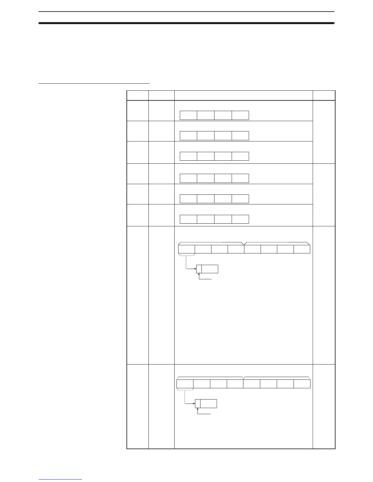
6-4-3 Expansion Data Area
Refer to the following for the expansion data area.
Expansion Data Area Allocation
Word Bit Description Page
I 00 to 15 No. of data transmission words (4-digit BCD)
x10
0
x10
1
x10
2
x10
3
144
I+1 00 to 15 Transmission data source word (4-digit BCD)
x10
0
x10
1
x10
2
x10
3
I+2 00 to 15 Transmission data destination address (4-digit BCD)
x10
0
x10
1
x10
2
x10
3
I+3 00 to 15 No. of data reception words (4-digit BCD)
x10
0
x10
1
x10
2
x10
3
145
I+4 00 to 15 Reception data source address (4-digit BCD)
x10
0
x10
1
x10
2
x10
3
I+5 00 to 15 Reception data destination word (4-digit BCD)
x10
0
x10
1
x10
2
x10
3
I+6
I+7
00 to 15 X-axis current position preset value (8-digit BCD)
When using the current position preset function at bit
05 of word n+5, specify the preset value in this area.
The data to be set depends on the minimum unit set
with the MC Support Software.
In the following example, the X axis is set to 100.
Minimum unit I+7 I+6 Remarks
1 0000 0100 Indicates 100
0.1 0000 1000 Indicates 100.0
0.01 0001 0000 Indicates 100.00
0.001 0010 0000 Indicates 100.000
0.0001 0100 0000 Indicates 100.0000
x10
4
x10
5
x10
6
x10
7
x10
0
x10
1
x10
2
x10
3
I+7 I+6
x10
7
3 2 1 0 bit
Sign bit
0: Positive
1: Negative
152
I+8
I+9
00 to 15 Y-axis current position preset value (8-digit BCD)
When using the current position preset function at bit
05 of word n+7, specify the preset value in this area.
Refer to the X-axis current position preset value.
x10
4
x10
5
x10
6
x10
7
x10
0
x10
1
x10
2
x10
3
I + 9 I + 8
x10
7
3 2 1 0 bit
Sign bit
0: Positive
1: Negative
152
Output
Interface Bits
Section 6-4
 Loading...


