20
2-4 Interface Circuits
The following tables provide specifications and circuit diagrams for the interface
circuits for the I/O and DRV connectors.
2-4-1 I/O and DRV Connector Circuits
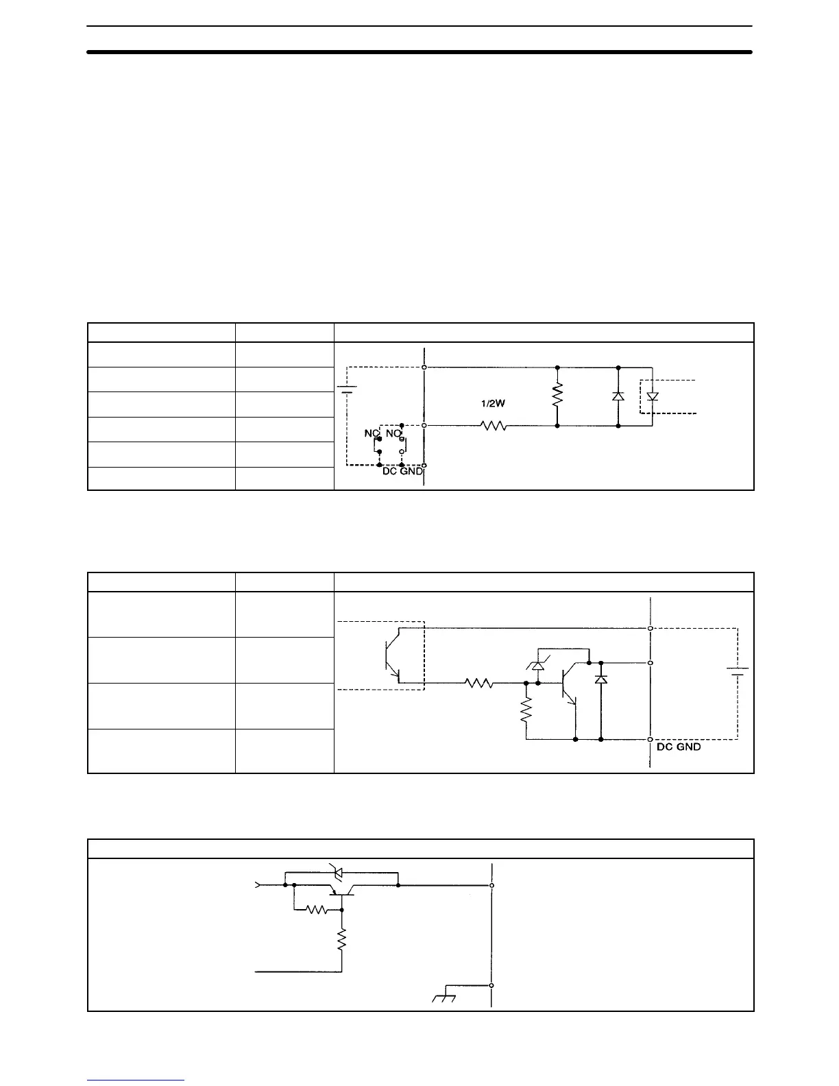
The circuit in the table below is used to interface the following inputs.
NC inputs: CWL, CCWL, STOP, and ALM (X and Y)
NO inputs: IN (1 and 2)
NC or NO inputs: ORG (X and Y)
Item Specification Circuit Configuration
Rated input voltage 24 VDC ± 10%
+24 V
Rated input current 4.3 mA
ON response time 1 ms max.
OFF response time 2.5 ms max.
The circuit in the table below is used to interface outputs RUN (X and Y) and
ALMRS (X and Y).
Item Specification Circuit Configuration
Max. switching capacity 50 mA/24 VDC
+24 V
Leakage current 0.1 mA max.
Output
Residual voltage 1.0 V max.
Photocoupler
External supply voltage 24 VDC ± 10%
The circuit in the table below is used to interface outputs SOUT (X and Y).
Circuit Configuration
SOUT (X and Y)
SGND (X and Y)
5 V
0 V
Interface Circuits
Section 2-4
 Loading...


