EasyManuals Logo

Omron C200H-MC221 User Manual

Omron C200H-MC221
305 pages
To Next Page IconTo Next Page
To Previous Page IconTo Previous Page
Page #41 background imageLoading...
Page #41 background image
21
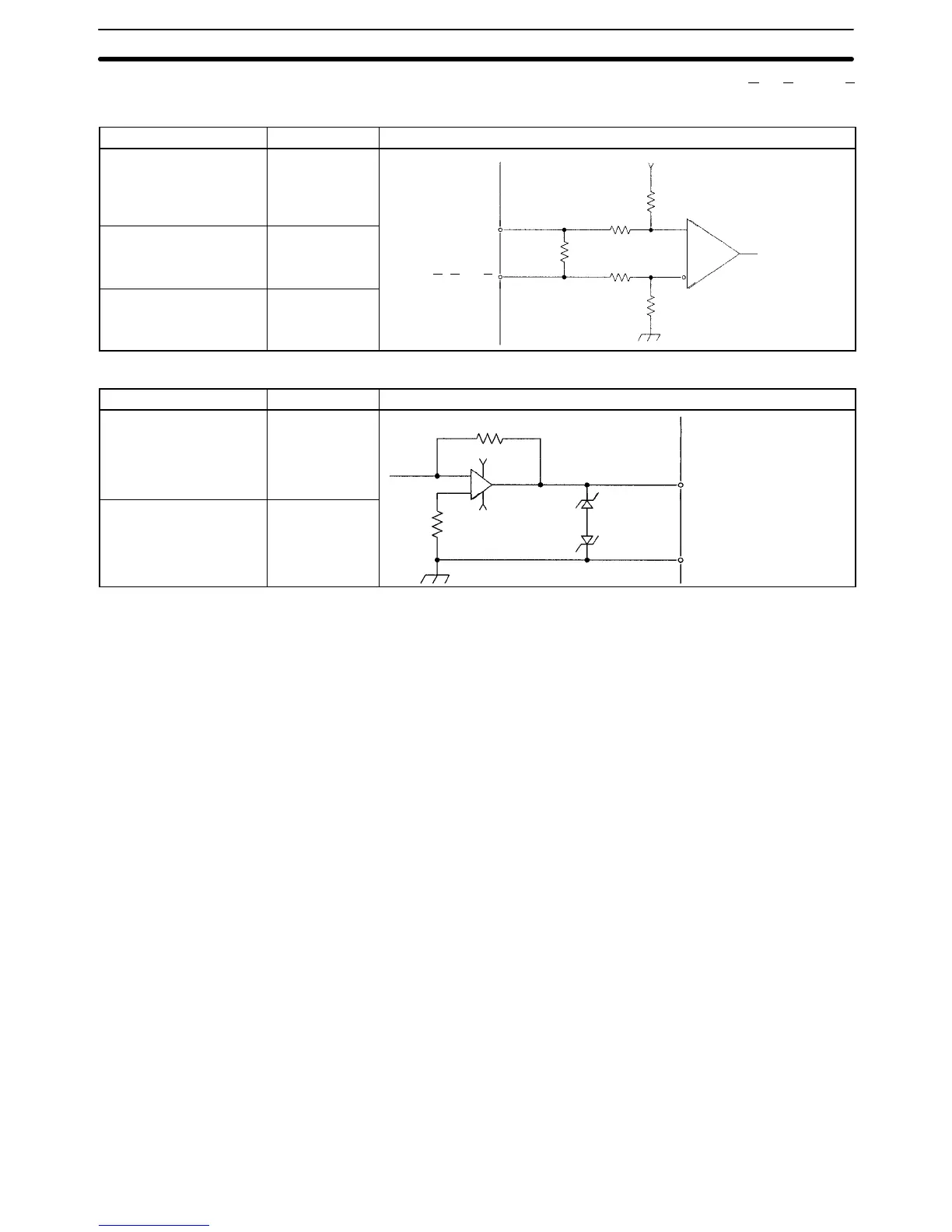
The circuit in the table below is used to interface phase inputs A, A, B, B, Z, and Z
(for the X and Y).
Item Specification Circuit Configuration
Signal level EIA RS-422-A
Standards
5 V
Input impedance 220 Ω
Phase A, B, or Z
Phase A, B, or Z
1/2W
220 Ω
Response frequency 250 kpps max.
Phase A
,
B
,
or Z
Line receiver
The circuit in the table below is used to interface outputs OUT (X and Y).
Item Specification Circuit Configuration
Output voltage 0 to ± 10 V
+15 V
X to Y OUT
Load impedance 10 KΩ min.
–15 V
X to Y AGND
Interface Circuits
Section 2-4

Table of Contents

Other manuals for Omron C200H-MC221

Questions and Answers:

Question and Answer IconNeed help?

Do you have a question about the Omron C200H-MC221 and is the answer not in the manual?

Omron C200H-MC221 Specifications

General IconGeneral
BrandOmron
ModelC200H-MC221
CategoryControl Unit
LanguageEnglish

Related product manuals