8
2-1 I/O Connector
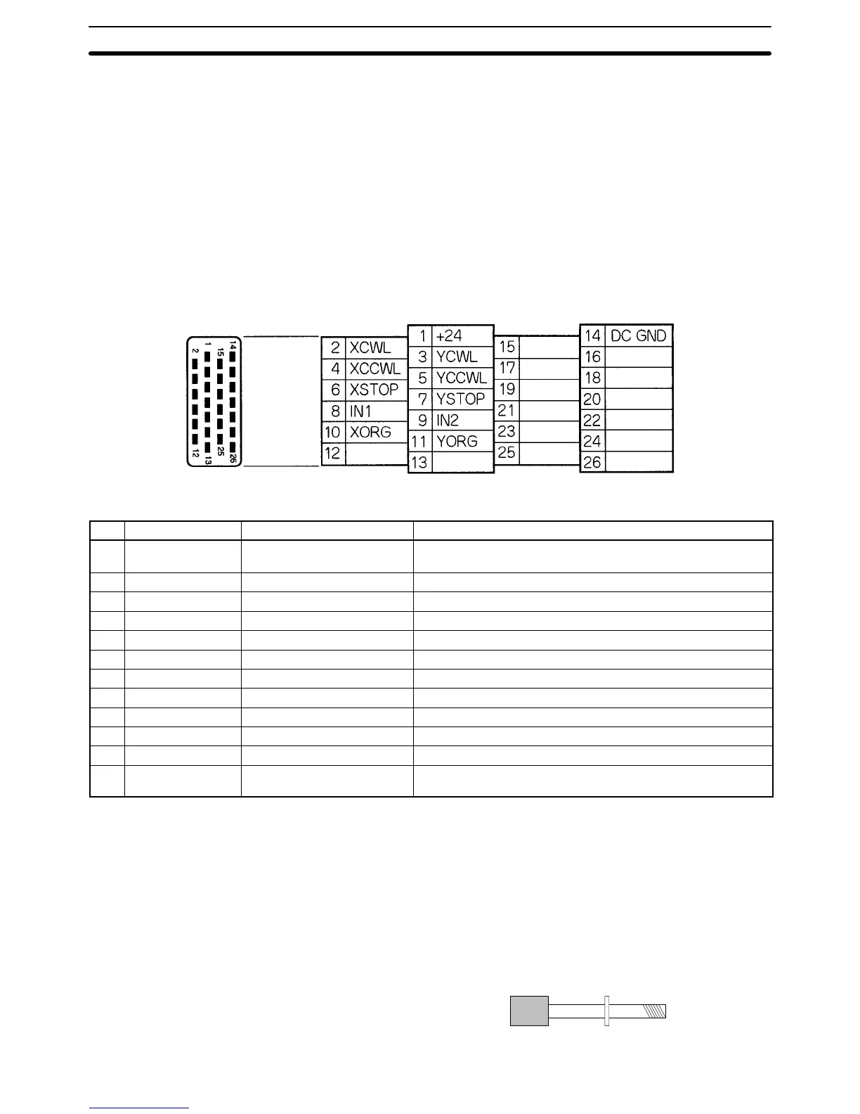
The I/O connector is used primarily for wiring to external I/O. There are connec-
tions for each axis’s CW and CCW limit inputs, emergency stop inputs, and ori-
gin proximity inputs, as well as general I/O connections. Dedicated cables and
terminals can be connected to the I/O connector.
2-1-1 Pin Allocation
A Bellows 26-pin half-pitch plug and case are included with the Unit.
Snap-on Connector The following connector and case are provided with the Unit.
1 connector: 10126-3000VE (Sumitomo 3M) (Model available in Japan.)
1 case: 10326-42F0-008 or 10326–52F0-008 (Sumitomo 3M) (Models available
in Japan.)
---
---
---
---
---
---
---
---
---
---
---
---
---
---
Pin Functions The following table explains the functions of the 26 pins in the I/O connector.
Pin Symbol
1
Name Function
1 +24V 24 VDC input Connects to the + terminal of the 24-VDC external power
supply.
2 XCWL(NC) X-axis CW limit input Limits movement of the X-axis in the CW direction.
3 YCWL(NC) Y-axis CW limit input Limits movement of the Y-axis in the CW direction.
4 XCCWL(NC) X-axis CCW limit input Limits movement of the X-axis in the CCW direction.
5 YCCWL(NC) Y-axis CCW limit input Limits movement of the Y-axis in the CCW direction.
6 XSTOP(NC) X-axis emergency stop input Invalidates the X-axis’s run output and stops it.
7 YSTOP(NC) Y-axis emergency stop input Invalidates the Y-axis’s run output and stops it.
8 IN1(NO) General input 1 General input 1
9 IN2(NO) General input 2 General input 2
10 XORG(NC,NO)
2
X-axis origin proximity input Used for the X-axis origin search.
11 YORG(NC,NO)
2
Y-axis origin proximity input Used for the Y-axis origin search.
14 DC GND 24 VDC input ground Connects to the – terminal (0 V) of the 24-VDC external
power supply.
Note 1. “NC” stands for normally closed and “NO” stands for normally open. Always
short normally closed input terminals which aren’t used.
2. Either NC or NO logic can be used. This setting is a mechanical parameter
(Origin Proximity Input Logic) set with MC Support Software.
2-1-2 Attaching a Connector
Attach a connector in one of the following ways.
• Use the connector (snap-on type) provided with the Unit.
• When using screws, use anti-electrostatic screws provided with the Unit.
Anti-electrostatic
screws (4 screws)
provided)
I/O Connector Section 2-1
 Loading...


