145
6-5-12 Word n+1 Bit 12: Reception Control Bit (All Tasks)
This bit is used to read data from the MC Unit.
The completion of data reading from the MC Unit can be confirmed with the
Reception Completed Flag.
This bit must be on hold until the Reception Completed Flag is turned ON.
This bit is available when the expansion data area is valid.
Data cannot be written to the MC Unit, read from the MC Unit, and written to the
flash memory at the same time. If they are instructed together, the instructions
are executed in the following order.
Priority: Data written to the MC Unit, data read from the MC Unit, and data written
to the flash memory.
Signal The Reception Control Bit settings have the following functions.
Signal Function
↑ Reads Data
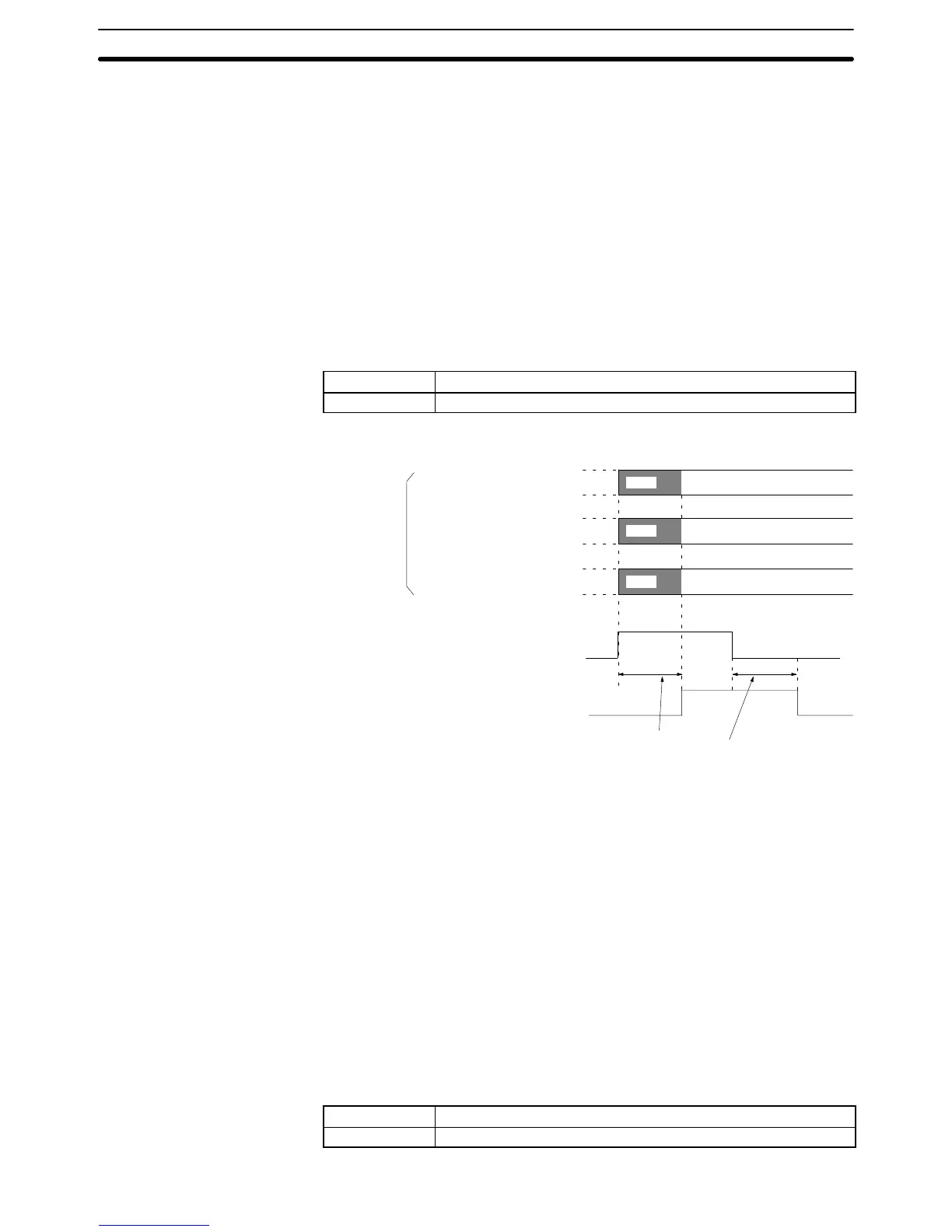
Timing Chart
Free
Free
Free
Set
Set
Set
No. of transfer words (I+3)
Source address (I+4)
Destination word (I+5)
Reception Control Bit
(n+1 bit 12)
Reception Completed Flag
(n+8 bit 08)
Required
information
is set in the
expansion
data area.
40 ms min. (Depends on the
volume of data)
Note Refer to Section 4 MC Unit Data.
6-5-13 Word n+1 Bit 13: Flash Memory Write Bit (All Tasks)
The position data of the MC Unit will be stored in the flash memory when this bit is
turned ON.
This bit must be on hold until the Flash Memory Write Completed Flag is turned
ON.
Data cannot be written to the MC Unit, read from the MC Unit, and written to the
flash memory at the same time. If they are instructed together, the instructions
are executed in the following order.
Priority: Data written to the MC Unit, data read from the MC Unit, and data written
to the flash memory.
Signal The Flash Memory Write settings have the following functions.
Signal Function
↑ Writes Data to Flash Memory
Interface Bit Specifics
Section 6-5
 Loading...


