159
Signal The Driver Alarm Reset Bit settings have the following functions.
Signal Function
1 (ON) The override data is valid.
0 (OFF) The override data is invalid.
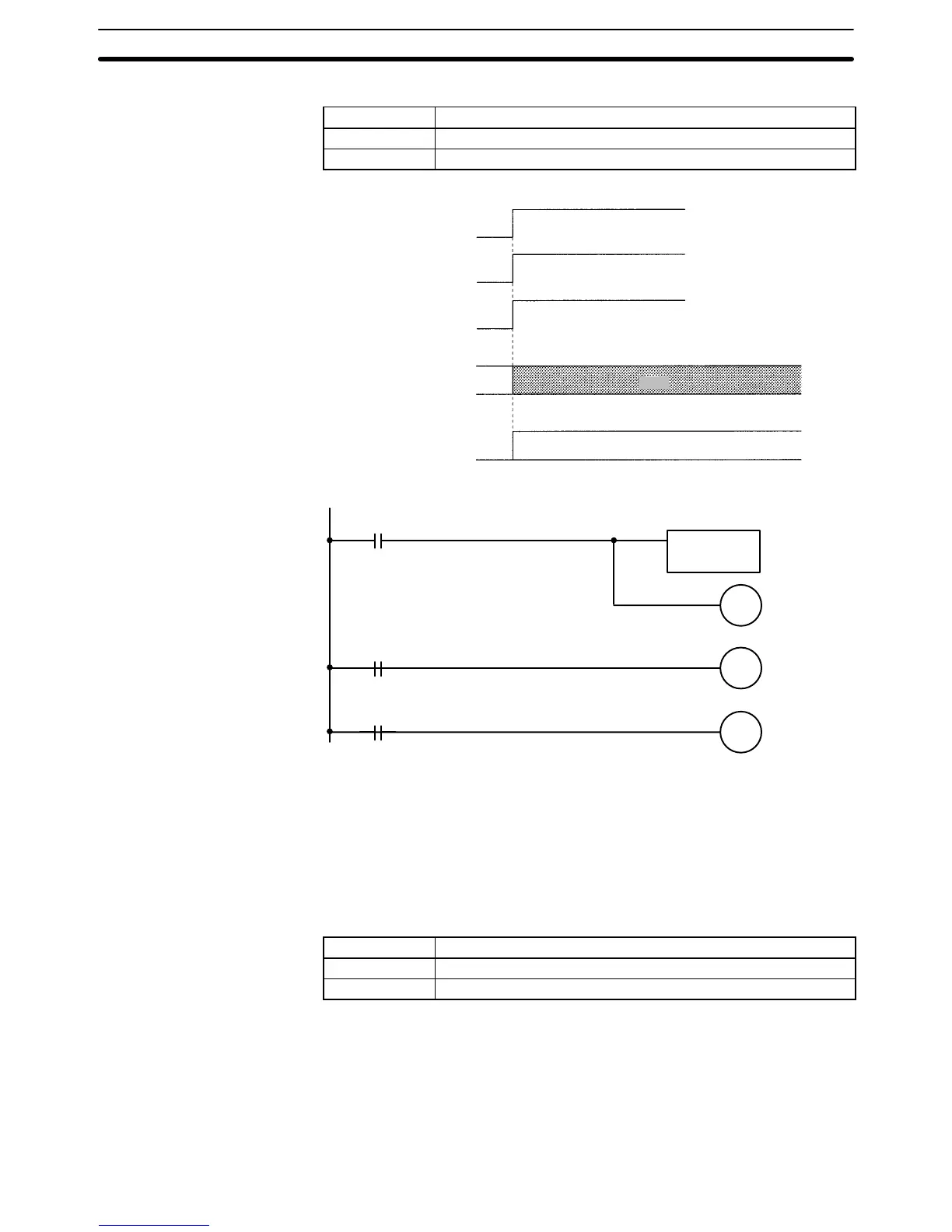
Timing Chart
Jogging Bit
(n+5 bit 03)
Jog Direction Bit
(n+5 bit 13)
Override Setting Bit
(n+5 bit 12)
Override setting
(n+4)
Jogging performed with the set override value (50.0%).
500
Program Example
OUT
(Sets the
override
value.)
OUT
(Sets the jog-
ging direc-
tion.)
OUT
(Starts the
jogging.)
Sets the override
data. (n+4)
Setting condition
Jogging condition
Jog Direction
condition
n+5
13
n+5
03
n+5
12
6-5-31 Word n+8 Bit 06: Transmission Completion Flag
This flag will be turned ON regardless of whether data has been transmitted nor-
mally or not.
This flag is used for the timing to turn the Transmission Control Bit ON.
This flag will not turn OFF until the Transmission Control Bit is turned OFF.
No data can be transmitted while this flag is ON.
Signal The Transmission Completion Flag settings have the following meanings.
Signal Function
↑ Data has been transmitted.
↓ No data is being written.
Note Refer to 6-5-11 Word n+1 Bit 11: Transmission Control Bit.
6-5-32 Word n+8 Bit 07: Data Transmission Error Flag
This flag will be turned ON when one of the following errors results during data
transmission.
• The number of transfer words, source word, or destination address is not in
BCD.
Interface Bit Specifics
Section 6-5
 Loading...


