86
2. The coordinate specification is set to absolute specification.
3. The operating mode is set to pass mode.
The settings won’t be switched to the ones above if function G26 is terminated
while in progress by the OPTIONAL END function (G74), FORCED BLOCK
END, or other function. The function is also considered to be in progress while
waiting for the M code reset.
The override is referred to only once at the start of G26. The feed rate cannot be
changed during operation.
Example Program ::
N010 G26 XY M500
::
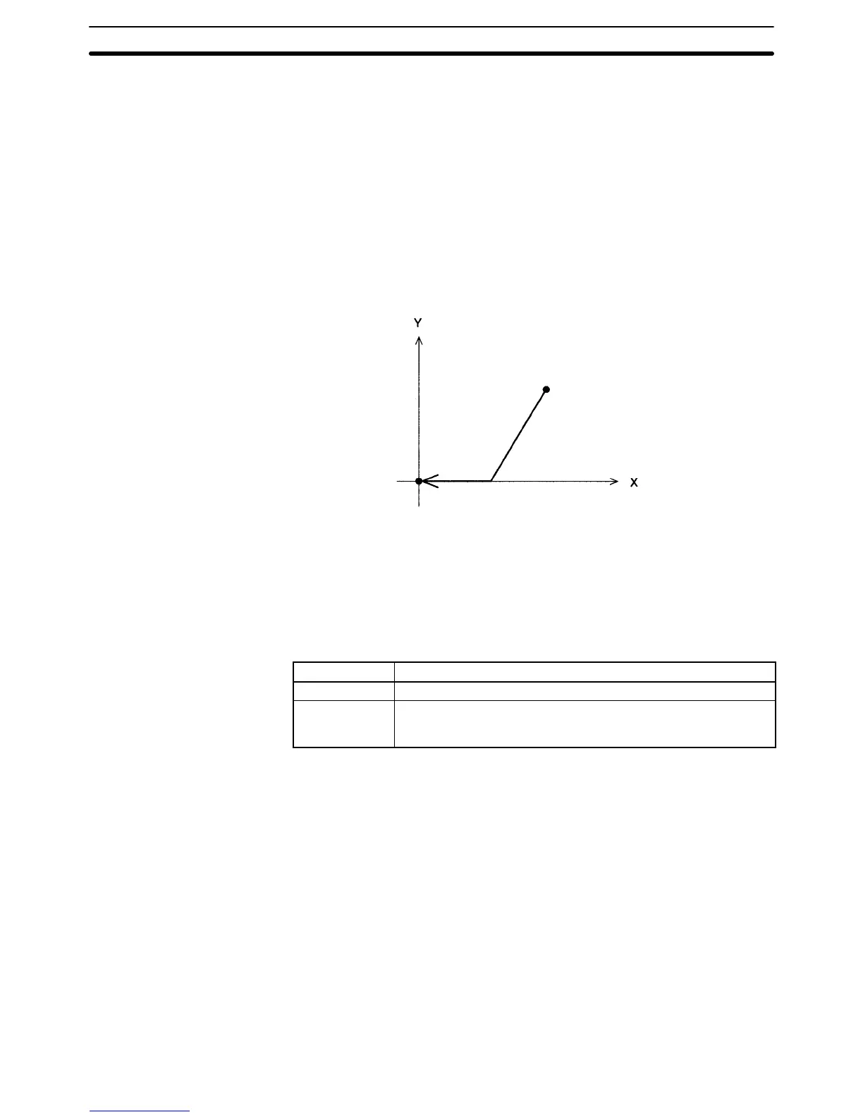
Reference origin
Reference coordinate system
5-5-9 G27: WORKPIECE ORIGIN RETURN
Moves to the workpiece origin.
Format G27_<Axis name ... >_[M<M code>]
Parameters The following table shows the possible settings for the parameters.
Parameter Possible settings
Axis name X and Y
M code* 000 to 999
(E00 to E31)
A0000 to A1999
Note Refer to 5-6 M-code Outputs for details on M codes.
Description This function moves the specified axes to the workpiece origin by PTP control.
The coordinate system and mode settings will be as follows after the return to the
workpiece origin:
1, 2, 3... 1. The coordinate system is set to the workpiece coordinate system.
2. The coordinate specification is set to absolute specification.
3. The operating mode is set to pass mode.
The settings won’t be switched to the ones above if function G27 is terminated
while in progress by the OPTIONAL END function (G74), FORCED BLOCK
END, or other function. The function is also considered to be in progress while
waiting for the M code reset.
The override is referred to only once at the start of G27. The feed rate cannot be
changed during operation.
G Functions
Section 5-5
 Loading...


