123
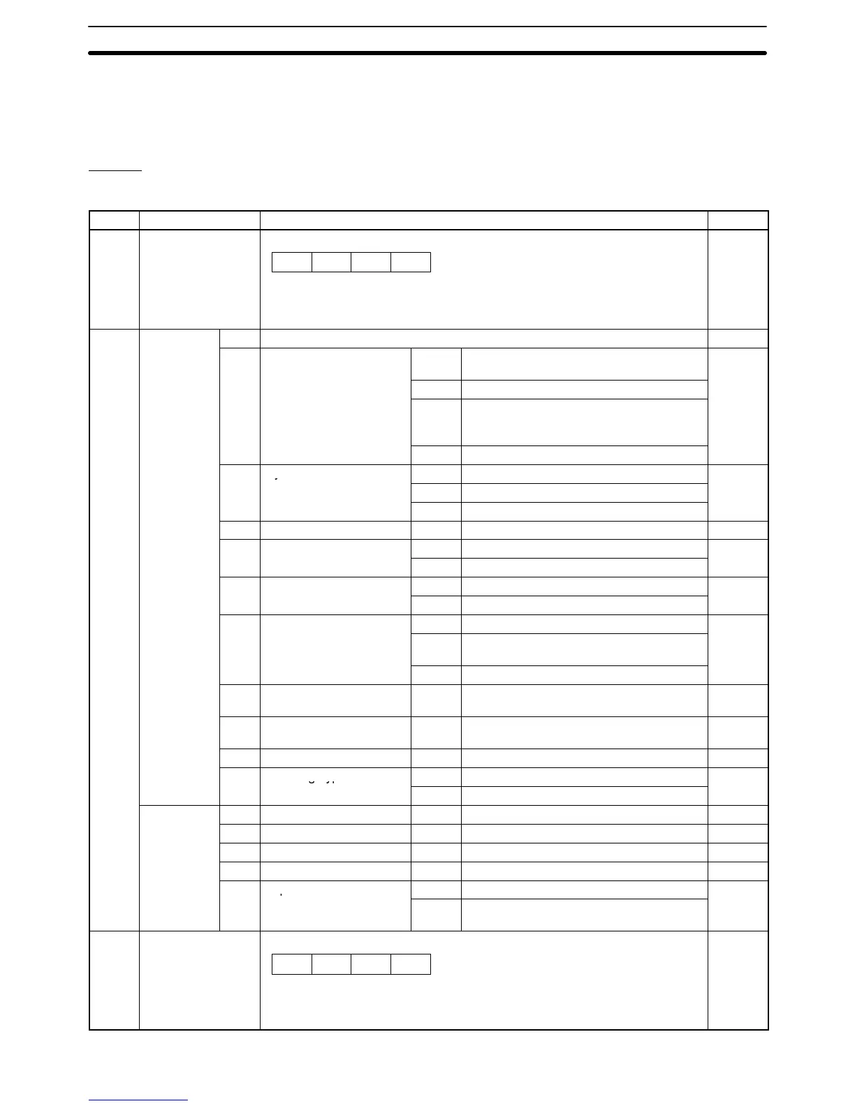
6-4-2 I/O Refresh Area
Refer to the following table for the I/O refresh area.
IR Bits
Output
Word Bit Description Page
n 00 to 15 Task 1 program numbers 0000 to 0999 (4-digit BCD)
Specifies program numbers executed in automatic mode. If the Control
Reception Bit is turned ON, a program number is read at the rising edge of the
cycle start to execute the program.
x10
0
x10
1
x10
2
0
135
n+1 Control Bits
00 Not used ---
for Task 1
01 Automatic/Manual Mode
↑ Any axes operating in manual mode will
decelerate to a stop.
134
1 Automatic mode
↓ When the MC program is being executed,
it will be stopped and any operating axes
will decelerate to a stop.
0 Manual mode
02 Cycle Start Bit
↑ Starts MC program execution.
135
1 Continues MC program execution.
0 Stops MC program execution.
03 Single Block 1 Executes a single block. 137
04 Forced Block End
↑ Forces an end to the block.
138
1 Prevents cycle start.
05 Pause
↑ Pauses execution.
139
1 Prevents cycle start.
06 M Code Reset Bit
↑ Resets the M code.
140
1 M code reset standby.
(Prevents M code output.)
↓ Clears M code reset standby.
07 Program Number Read
Bit
1 Reads the program number. 142
08 Teaching Address Set
Bit
↑ Sets the address when teaching. 142
09 Teaching Bit ↑ Starts teaching. 142
10 Teaching Type Bit
1 Current position (feedback value)
143
0 Target position
All tasks
11 Transmission Control Bit ↑ Starts transmission. 144
common 1
12 Reception Control Bit ↑ Starts reception. 145
13 Flash Memory Write Bit ↑ Starts writing data to the flash memory. 145
14 Error Reset Bit ↑ Resets an error. 146
15 Expansion Data Read
1 Refreshes the expansion data area.
147
Bit
0 Leaves the expansion area without
refreshing.
n+2 00 to 15 Task 2 program numbers 0000 to 0999 (4-digit BCD)
Specifies program numbers executed in automatic mode. If the Control
Reception Bit is turned ON, a program number is read at the rising edge of
the cycle start to execute the program.
x10
0
x10
1
x10
2
0
135
Interface Bits
Section 6-4