3
1-2 Indicators
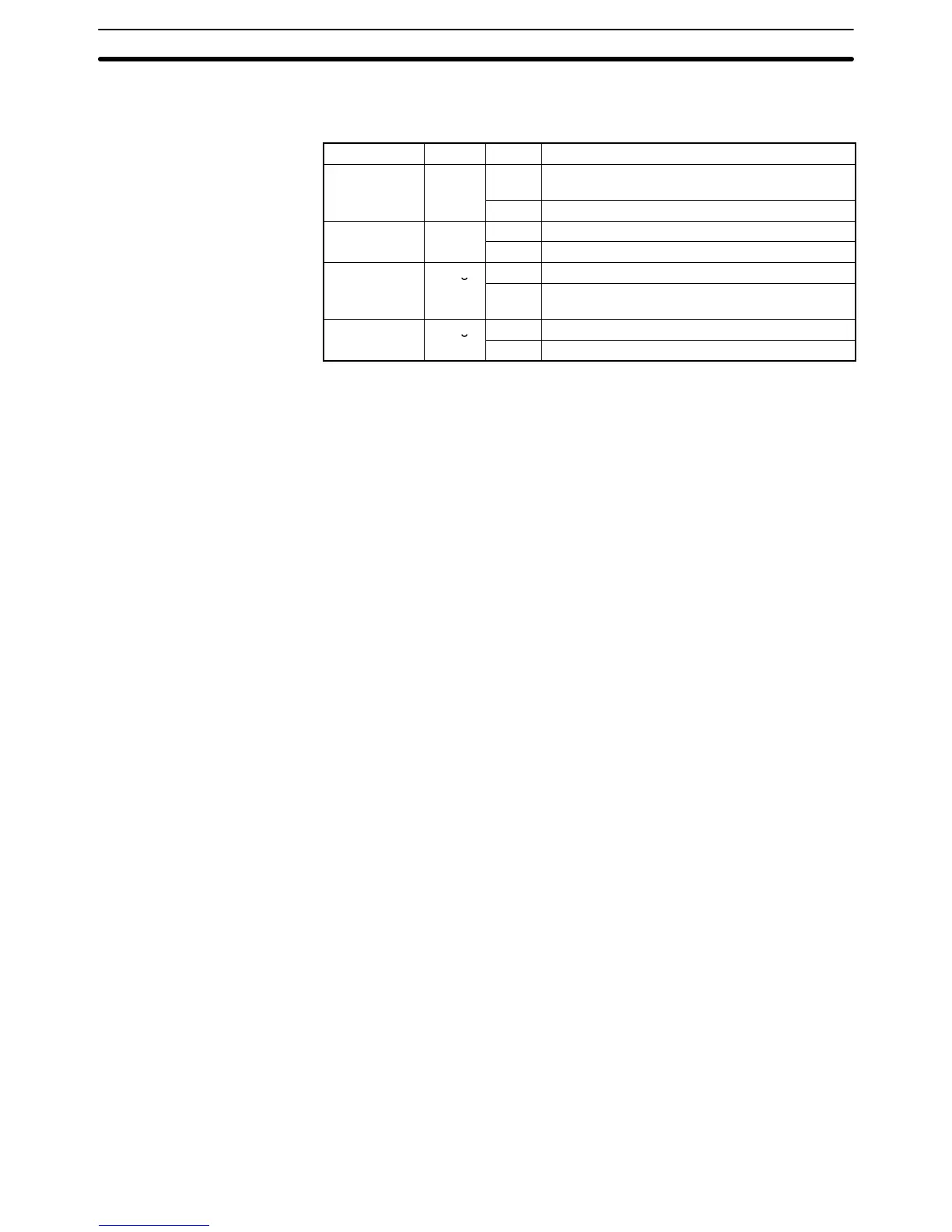
The following table shows the meaning of the indicators on the front of the Unit.
Indicator Color Status Meaning
RUN Green
ON Initialization was completed normally and the
connection of the MC Unit and the PC is normal.
OFF The MC Unit or PC has an error.
ERR Red
ON An error occurred in the MC Unit.
OFF The MC Unit is operating normally.
X or Y CCW Orange
ON The motor is rotating counterclockwise.
OFF The motor is stopped or rotating clockwise.
Note A fatal error of the MC Unit will be indicated by the XCCW, YCCW, XCW, or YCW
indicator. Refer to 10-1 Error Indicators for details.
1-3 Setting the Unit Number
The unit number setting determines which IR area and DM area words are allo-
cated to the MC Unit. These words are used to transfer data between the PC and
MC Unit and are known as the “PC data area interface.”
Allocated Words The interface area varies with the type of the PC to which the MC Unit is
mounted. Refer to the following examples. Refer to Section 6 PC Data Area
Interface for more details.
C200H/C200HS IR area: 20 words beginning with word n (100 + 10 x unit no.)
DM area: 2 words beginning with word m (1,000 + 100 x unit no.)
C200HX/C200HG/C200HE IR area: 20 words beginning with word n (100 + 10 x unit no.) if the unit no. is 8
or less.
20 words beginning with word n (400 + 10 x (unit no. – 10)) if the unit
no. is 10 or larger.
DM area: 2 words beginning with word m (1,000 + 100 x unit no.)
Note 1. The unit number can be set from 0 to F (A to F are 10 to15 respectively).
2. The unit number must be from 0 to 8 if the MC Unit is mounted to the C200H
or C200HS.
The unit number must be from 0 to 8 or from A to E if the MC Unit is mounted
to the C200HX, C200HG, or C200HE.
If the unit number is set to 9 or F, an error will occur when the power is turned
ON.
3. Be sure that none of the CPU Bus Units’ unit numbers have been duplicated
when connecting more than one CPU Bus Unit to a single PC.
Setting the Unit Number
Section 1-3
 Loading...


