H5L
H5L
263
Installation
Wiring
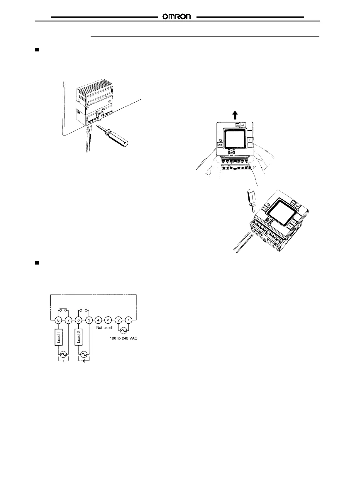
Wiring From the Rear
Perform wiring from the rear of the unit when the unit is flush
mounted.
Wiring From the Front
Perform wiring from the front of the unit when the unit is track orsur-
face mounted.
1. Loosen the screw on the left side of the front.
2. Slide the upper part of the unit approx. 15 mm upward.
3. After the terminals appear, perform wiring.
4. Return the upper part of the unit to the original position and
tighten the screw.
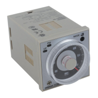
Connections
Connect the power supply between terminals
A
and
B
, the load for
the first circuit between terminals
G
and
H
, and the load for the se-
cond circuit between terminals
E
and
F
. Terminals
C
and
D
are no
connects.
Note: To each load, connect the power supply for load.