H3CA
H3CA
121
Precautions
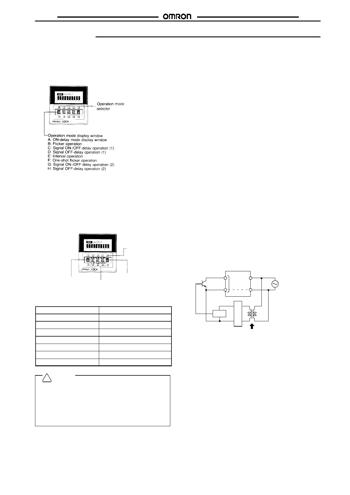
How to Change Operation Mode
Operate the pushbuttons of the thumbwheel switch, located at the
leftmost position on the front panel to set theoperation mode. Eight
operation modes (A, B, C, D, E, F, G, and H) are selectable and the
selectedoperation modeis displayedin the operation modedisplay
window.
Note: The operation mode is fixed to “A” for H3CA-8H.
How to Change Time Unit and Rated Time
Operate the pushbuttons of the rightmost thumbwheelswitch to se-
lect the desired time unit. Seven time units (0.1 s,s, 0.1 m, m, 0.1 h,
h, or 10 h) are selectable and the selected time unit is displayed in
the time unit display window. The desired rated time is specified by
operating the three thumbwheel switches in the middle of the front
panel. The range of rated time is 001 to 999 for each unit.
Time unit
selector
Time unit display
window
0.1s,s,0.1m
0.1h,h,10h
Rated time display
window
001 to 999
Rated time
selector
Time Unit and Rated Time
Time unit
Rated time
0.1 s 0.1 to 99.9 s
s 1to999s
0.1 min 0.1 to 99.9 min
min 1to999min
0.1 hrs 0.1 to 99.9 hrs
hr 1 to 999 hrs
10 hrs 10 to 9,990 hrs
Caution
1. Do not change the time unit, rated time, or operation mode
while the timer is in operation. Otherwise, the timer may
malfunction or be damaged. Be sure to turn off the power
supply to the timer before changing the timer unit, rated
time or operation mode.
2. Note that output will be generated in C, D, E, G, or H mode
even if the rated time is set to 000. No output will be gener-
ated in A, B, or F mode.
Connecting the Operating Power Supply
The H3CA-8
j
contains a capacitor-drop power circuit. Use a sinu-
soidal powersupply withacommercialfrequency. Donot usepower
supplies with a high frequency component (such as inverter power
supplies) for Timers with 100 to 240-VAC specifications. Using
these power supplies can damage internal circuits.
Thepower supply connections to the H3CA-A and H3CA-FAcanbe
made without regard to polarity for bothAC andDC powersupplies;
just connect to the specified terminals (2 and 10, or A1 and A2).
When connecting a DC power supply to the H3CA-8 or H3CA-8H,
however, the polarity must be connected as indicated.
Although thereis awide range of power connectable to theH3CA-A
and H3CA-FA, besure that there is no inductive voltage or residual
voltage applied to the timer power supply terminals (2 and 10, or A1
and A2) when the power switch is turned OFF. (Inductive voltage
can be generated in the power supply line if it is placed in parallel
with high-voltage or power lines.)
A DC power supply can be connected if its ripple factor is 20% or
less and the mean voltage is within the rated operating voltage
range of the Timer.
Connect the power supply voltage through a relay or switch in such
a way that the voltage reaches a fixed value at once or the Timer
may not be reset or a timer error could result.
H3CA-8andH3CA-8HTimerswithACspecificationsareequivalent
to capacitor loads. When switching the Timer power supply with an
SSR, usean SSRwithawithstand voltageof twicethepowersupply
voltage.
Input/Output
Theoperationoftheoutput contacts varies withthe operationspeci-
fications. Before making connections, check the operation specifi-
cations and operating conditions using the application examples
provided.
The H3CA-A and H3CA-FA do not use transformers. Simultaneous
inputting power from two or more power supplies to separate timers
or counters from a single input contact or transistor is not possible.
For the power supply ofan input device, use an isolating transform-
er, of which the primary and secondary windings are mutually iso-
lated and the secondary winding is not grounded.
H3CA-A/-FA
Input
terminal
Power supply
Circuit
Isolation transformer is required.
Rectifier circuit
A transformer is not used in the power supplies for the H3CA-A and
H3CA-FA. Youcanthereforereceiveanelectricalshock bytouching
the input terminals when the power supply voltage is being applied.
Take adequate precautions to protect against electrical shock.
Inputs to input signal terminals are made by shorting the individual
input terminals to the common terminal (terminal 3 for the H3CA-A
or terminal (X) for the H3CA-FA). Internal circuits may be damaged
if connections are made to any other terminals or if voltages areap-
plied.
If contacts are used to short the terminals, they will be switching a
low voltage (approximately 5 VDC) and current (approximately 100
&
A). You must therefore use high-reliability contacts with a contact
resistance of 1 k
$
or less when shorted and residual voltage of 1V
maximum when shorted.
The reset input will take priority if both the set and reset inputs are
turned ON simultaneously.
!

 Loading...


