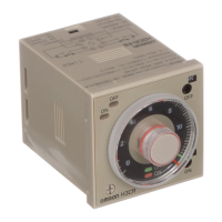
H3T
H3T
147
Timing Chart
Standard Operation
Outputs areproduced when the settimeis reached after power(S
4
)
is applied (to terminals 13 and 14 or terminals 13, 14, and 15).
Anexternalresistorcanbeconnectedbetweenterminals21 and24;
leaveterminals21and22open(referto followinginformation onex-
ternally connected resistor and operation time). When performing
an external reset, short-circuit terminals 1 and 13. The current will
be approximately 1 mA, so any contacts that are controlled by the
output must be highly reliable. When controlling a transistor, the
I
CEO
must be 0.1 mA and the V
CE
(sat) must be 1.0 V or less.
For 12 VDC, short-circuit
the terminal section by the
dotted line.
When Connecting External Resistor
Note: Terminal 24 cannot be used.
Note: Terminal 22 cannot be used.
Power S
1
(13 to 14, or
13 to 14, 15)
ON OFF ON
1ms
Reset input
S
2
(1 to 13)
Control output
(11to12)
Set time Set time
24 VDC
24 VDC
Integration Operation
The variable resistor connection can be opened to interrupt the tim-
eroperation, thus enablingintegration operation. Interrupt the timer
operation by opening the connection between terminals 21 and 22
when using the interval variable resistor, or by opening the connec-
tion between terminals 21 and 24 when using an external resistor.
Timer operation will continue when the connection is closed again.
When Connecting External Resistor
Note: Terminal 24 cannot be used.
Note: Terminal 22 cannot be used.
24 VDC
1ms
T
1
T
2
T
3
T
4
ON ONOFF
Tn
1ms
Open
Open
Short-circuitShort-circuitShort-circuit
Set time (T
1
+T
2
,orT
3
+T
4
)
Power S
1
(13to14,or
13 to 14, 15)
Reset input
S
2
(1 to 13)
Control output
(11to12)
S
3
(21to22,or
21 to 24)
24 VDC

 Loading...