H5CN
H5CN
208
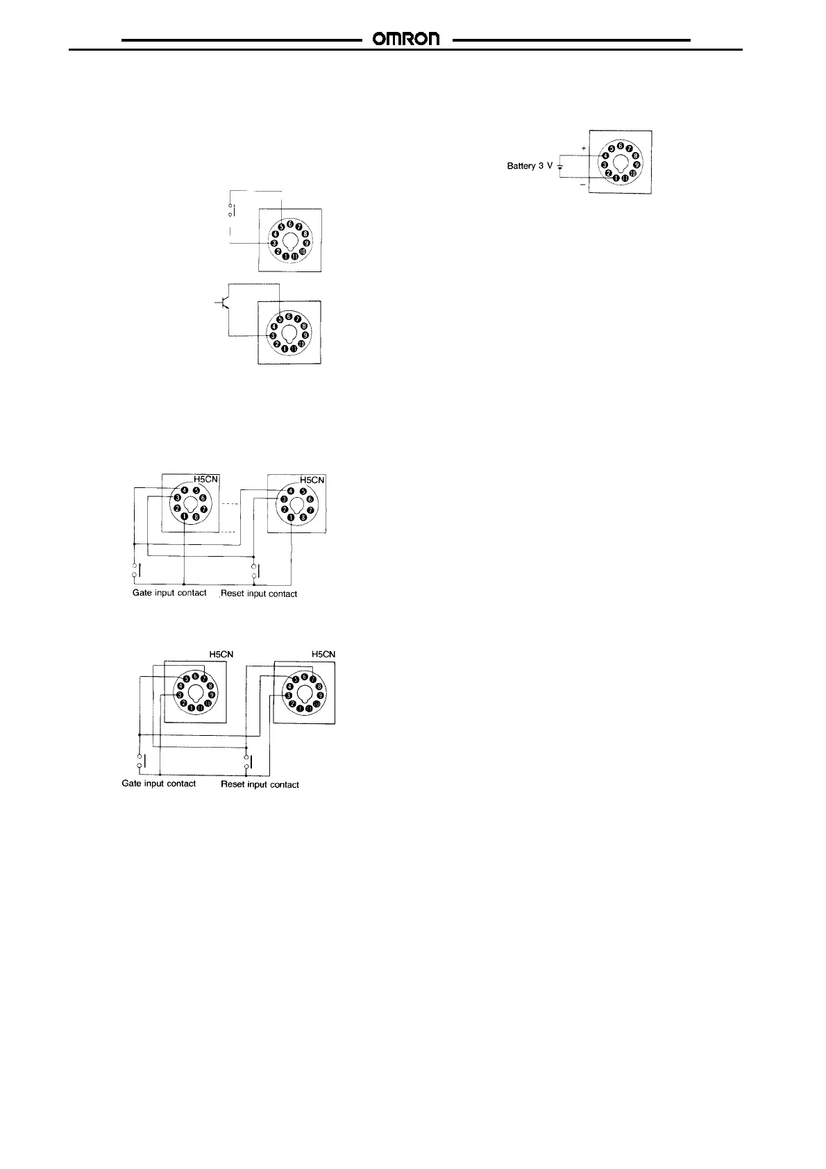
Model With Backup Power for Memory Protection
Connection of the gate input contact or an open collector transistor
between terminals
C
and
E
permits the timer operation to be inter-
rupted while the contact or transistor is in the ON state. The same
recommendations as mentioned above apply onthe use of the gate
input contact or transistor. Use a gate input contact with a short
bounce time because the contact bounce time causes an error in
the operate time of the timer for a period equalling the bounce time.
Gate input contact
(Timer stops when
contact is made.)
Gate input transistor
(Timer stops when
transistor is ON.)
Simultaneous Input to a Number of H5CN Tim-
ers with the Same Contact
Withonecontact,areset orgate input maybeappliedtotwo ormore
H5CN Timers as shown below.
Model Without Backup Power for Memory Protection
Model With Backup Power for Memory Protection
Battery Connection
Connect the Y92S-20 backup battery between terminals
A
and
D
,
paying attention to the polarities.
Battery Connections When Recording Interrup-
tions
Always connectabatterywhenusingUnits witha powerinterruption
recording function. Any 3-V battery may be used, but the time the
interruptionis recordedfor willdependonthecapacityof thebattery.
When using the Unit for the first time after purchase, apply power
and reset the Unit once before using it. When power is applied for
the first time, outputs may be produced, so do not connect the out-
put terminals.
If a power interruption continues for 10 minutesor morewhen abat-
teryis not connected, thedisplay mayflash,the count valueanddis-
plays may be meaningless, and outputs may be produced unpre-
dictably even if the power supply recovers. If this happens, apply
power to the reset input before using the Unit further.
When connecting the battery using a Socket (P2CF-11 or
P3GA-11), check the terminal numbers on the Socket and connect
the positive side of the battery to terminal 4 and the negative side to
terminal 1.

 Loading...


