H3CR-H
H3CR-H
54
Engineering Data
Reference: A maximum current of 0.15 A can be switched at 125 VDC (cos
%
=1)
and a maximum current of 0.1 A can be switched if L/R is 7 ms. In
both cases, a life of 100,000 operations can be expected.
The minimum applicable load is 10 mA at 5 VDC (failure level: P).
Load current (A)
30 VDC L/R = 7 ms
250 VAC/30 VDC
(cos
%
=1)
250 VAC (cos
%
=0.4)
Switching operations (x 10 )
3
10,000
5,000
1,000
500
100
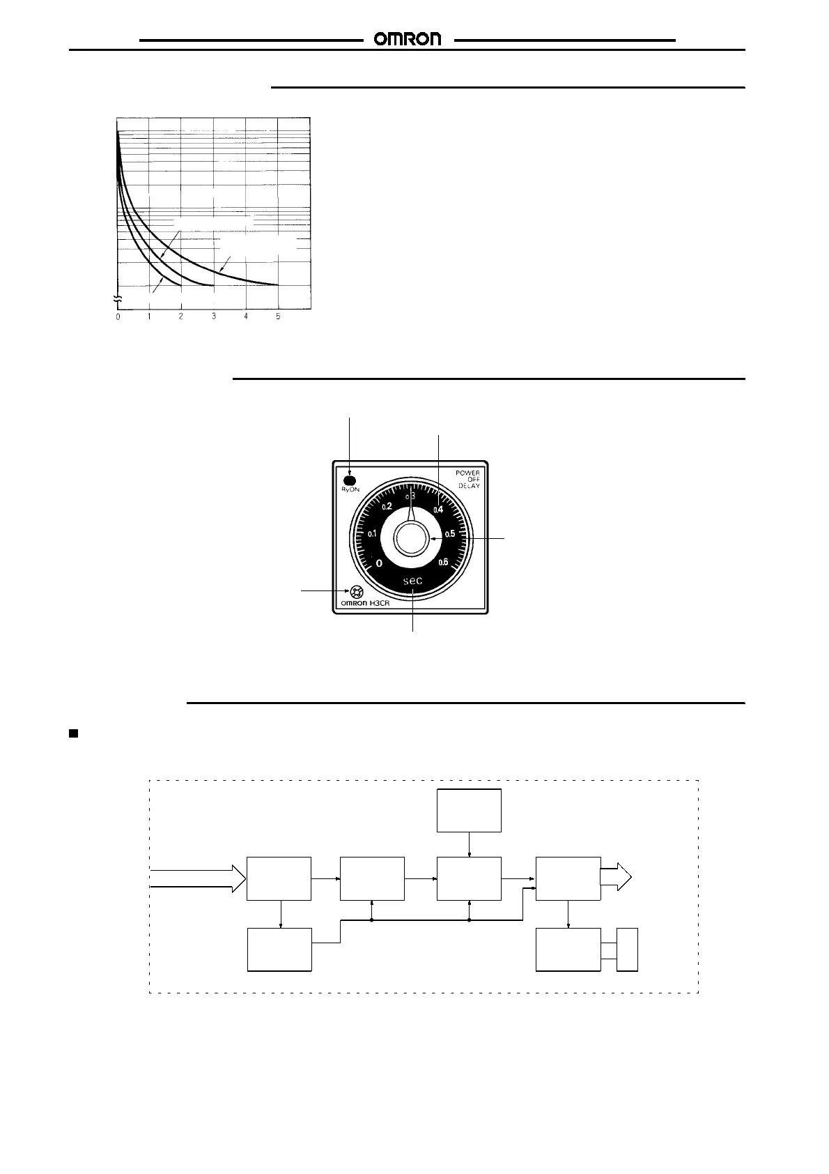
Nomenclature
Time range selector (select
one from 0.6, 1.2, 6, 12)
Output indicator (red)
Scale range display windows
Time unit display
S-series: sec
M-series: min
Time setting knob (for setting
power OFF-delay time)
Operation
Block Diagrams
Without Reset Input (H3CR-H8L)
LCD
Time range
selector
Power supply
circuit
Oscillation
circuit
Counting
circuit
Output
circuit
Power failure
detection circuit
Indicator
circuit
AC (DC) input
Output
indicator

 Loading...


