H3CR-H
H3CR-H
53
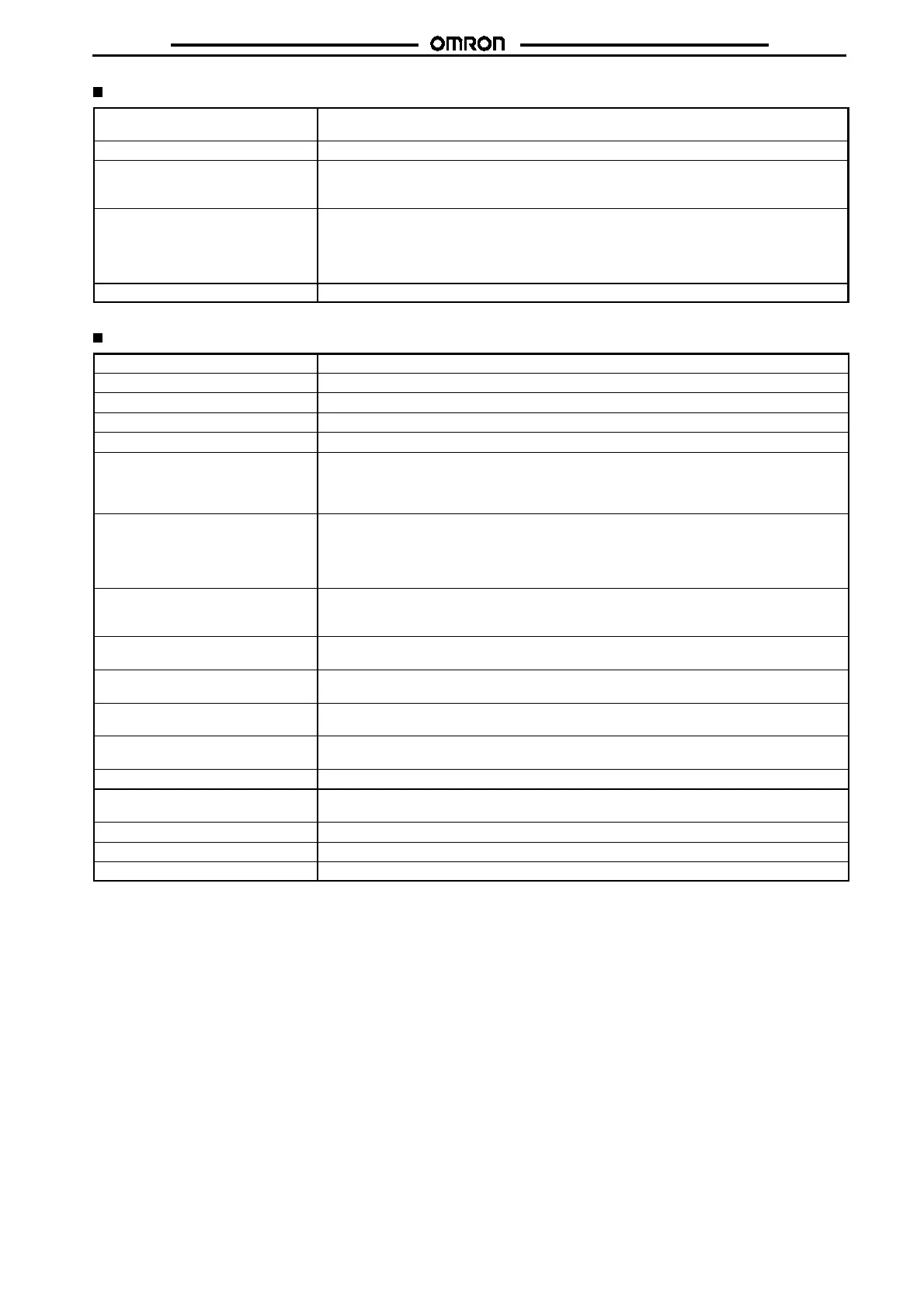
Ratings
Rated supply voltage (see note) 100 to 120 VAC (50/60 Hz), 200 to 240 VAC (50/60 Hz), 24 VAC/VDC (50/60 Hz), 48 VDC,
100 to 125 VDC
Operating voltage range 85% to 110% of rated supply voltage
No-voltage input ON-impedance: 1 k
$
max.
ON residual voltage: 1 V max.
OFF impedance: 500 k
$
min.
Power consumption 100 to 120 VAC: 0.18 VA (100 VAC applied)
200 to 240 VAC: 0.25 VA (200 VAC applied)
24 VAC/DC: 0.24 VA (24 VAC applied)/140 mW (24 VDC applied)
48 VDC: 130 mW (48 VDC applied)
100 to 125 VDC: 330 mW (125 VDC applied)
Control outputs Contact output: 5 A at 250 VAC, resistive load (cos
%
=1)
Note: A power supply with a ripple of 20% max. (single-phase power supply with full-wave rectification) can be used with each DC Model.
Characteristics
Accuracy of operating time
!
0.3% FS max. (
!
0.3% FS
!
10 ms in ranges of 0.6 and 1.2 s)
Setting error
!
5% FS
!
0.05 s max.
Influence of voltage
!
0.5% FS max. (
!
0.5% FS
!
10 ms in ranges of 0.6 and 1.2 s)
Influence of temperature
!
2% FS max. (
!
2% FS
!
10 ms in ranges of 0.6 and 1.2 s)
Insulation resistance 100 M
$
min. (at 500 VDC)
Dielectric strength 2,000 VAC, 50/60 Hz for 1 min (between current-carrying metal parts and exposed
non-current-carrying metal parts)
2,000 VAC, 50/60 Hz for 1 min (between control output terminals and operating circuit)
1,000 VAC, 50/60 Hz for 1 min (between contacts not located next to each other)
Impulse withstand voltage 3 kV (between power terminals) for 100 to 120 VAC, 200 to 240 VAC, 100 to 125 VDC;
1 kV for 24 VAC/DC, 48 VDC
4.5 kV (between current-carrying terminal and exposed non-current-carrying metal parts) for
100 to 120 VAC, 200 to 240 VAC, 100 to 125 VDC;
1.5 kV for 24 VAC/DC, 48 VDC
Noise immunity
!
1.5 kV (between power terminals) and
!
600 V (between input terminals), square-wave noise
by noise simulator (pulse width: 100 ns/1
&
s, 1-ns rise);
!
1 kV (between power terminals) for 48 VDC
Static immunity Malfunction:8 kV
Destruction:15 kV
Vibration resistance Destruction:10 to 55 Hz with 0.75-mm single amplitude each in three directions
Malfunction:10 to 55 Hz with 0.5-mm single amplitude each in three directions
Shock resistance Destruction: 980 m/s
2
(100G) each in three directions
Malfunction:98 m/s
2
(10G) each in three directions
Ambient temperature Operating:--10
"
Cto55
"
C (with no icing)
Storage: --25
"
Cto65
"
C (with no icing)
Ambient humidity Operating: 35% to 85%
Life expectancy Mechanical:10 million operations min. (under no load at 1,200 operations/h)
Electrical: 100,000 operations min. (5 A at 250 VAC, resistive load at 1,200 operations/h)
Case color Light Gray (Munsell 5Y7/1)
Enclosure ratings IEC: IP40
Weight Approx. 120 g

 Loading...


