40 Solid-state Power OFF-delay Timer H3CR-H
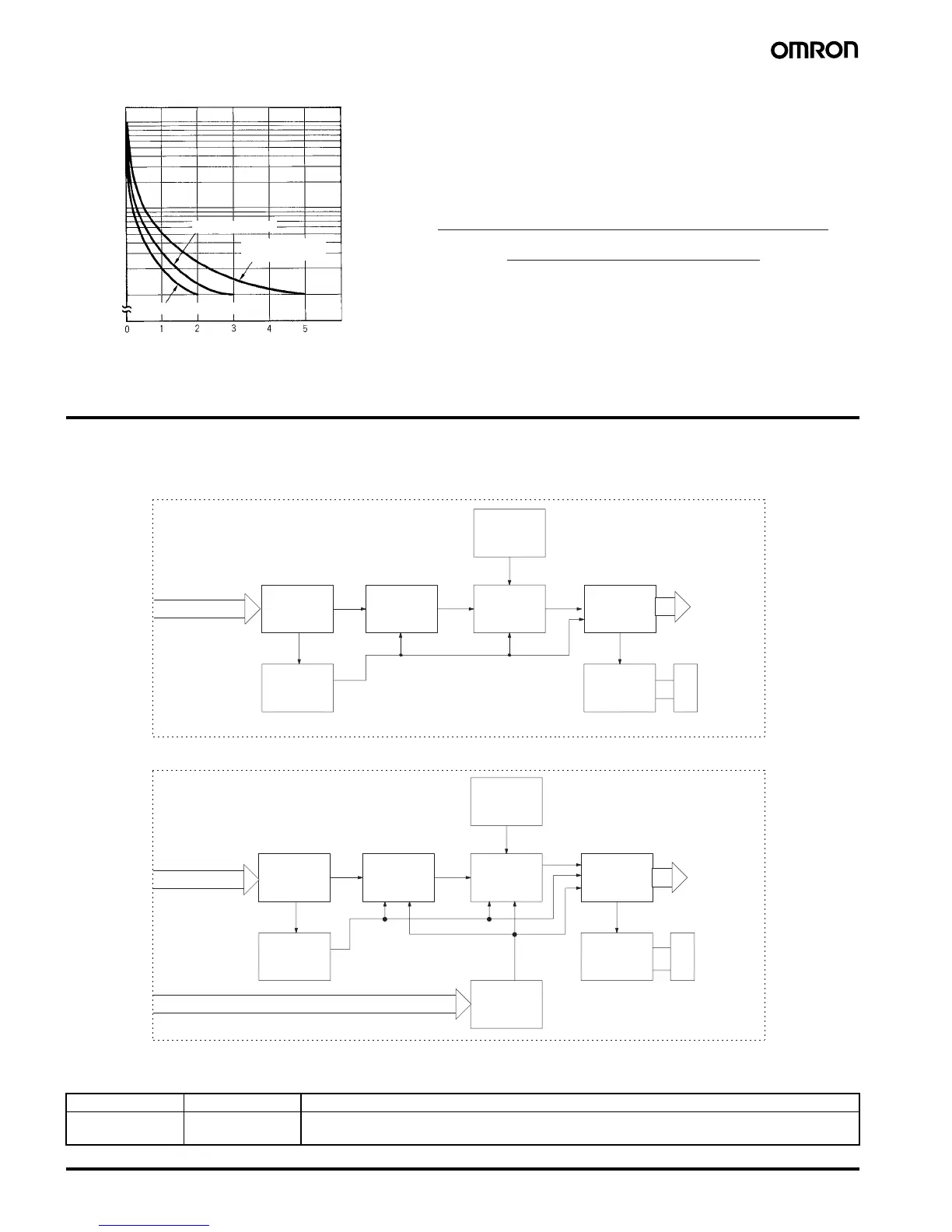
■ Life-test Curve
Connections
■ Block Diagrams
■ I/O Functions
10,000
5,000
1,000
500
100
Load current (A)
30 VDC L/R = 7 ms
250 VAC (cosφ = 0.4)
Switching operations (× 10
3
)
250 VAC/30 VDC
(cosφ = 1)
Reference: A maximum current of 0.15 A can be switched at 125 VDC (cosφ = 1)
and a maximum current of 0.1 A can be switched if L/R is 7 ms. In
both cases, a life of 100,000 operations can be expected.
The minimum applicable load is 10 mA at 5 VDC for H3CR-H8L/-HRL
and 100 mA at 5 VDC for H3CR-H8RL (failure level: P).
Without Reset Input (H3CR-H8L)
LCD
AC (DC) input
Power supply
circuit
Power failure
detection circuit
Oscillation
circuit
Time range/
unit selector
Counting
circuit
Output
circuit
Indicator
circuit
Output
indicator
With Reset Input (H3CR-H8RL/-HRL)
LCD
Input circuit
AC (DC) input
Reset input
Power supply
circuit
Power failure
detection circuit
Oscillation
circuit
Time range/
unit selector
Counting
circuit
Output
circuit
Indicator
circuit
Output
indicator
Inputs Reset Turns off the control output and resets the elapsed time.
Outputs Control output Operates instantaneously when the power is turned on and time-limit resets when the set time is up
after the power is turned off.