Solid-state Multi-functional Timer H3DS-M/-S/-A B-19
Timers
Note: The start input of the H3DS-ML@ model is activated by applying a voltage to B1 and A2 terminals.
The voltage can be applied by turning on the contact between B1 and A1 (Refer to Terminal Arrangement).
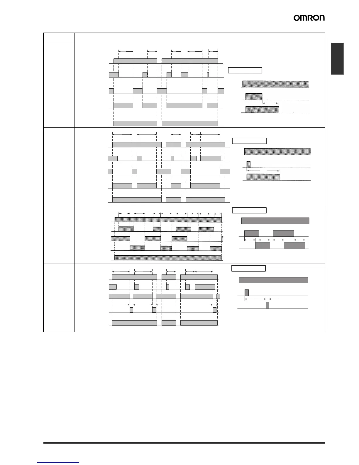
Operating
mode
Timing chart
D:
Signal
OFF-delay
E: Interval
G:
Signal
ON/OFF-
delay
J:
One-shot out-
put
(ON delay)
*
Power (A
1
and A
2
)
ttt–a t–a t–a
Basic operation
Power
Output
* Start input is valid and re-triggerable while the
Timer is in operation.
Start
t
Power indicator
Start (B
1
and A
2
)
(see note)
Output relay: NC
15 and 16
Output relay: NO
(output indicator)
15 and 18
**
*
Power (A
1
and A
2
)
tt tt–at–a
Basic operation
Power
Output
* For power-on operation, impose voltage to the
Start input. The Timer starts operating at the
moment the power is turned on.
** Start input is valid and re-triggerable while the
Timer is in operation.
Start
t
Power indicator
Start (B
1
and A
2
)
(see note)
Output relay: NC
15 and 16
Output relay: NO
(output indicator)
15 and 18
*
Power (A
1
and A
2
)
Power indicator
tt tt–a t–a t–a
Basic operation
Power
Output
* Start input is valid and re-triggerable while the
Timer is in operation.
Start
ttt t
tt
Start (B
1
and A
2
)
(see note)
Output relay: NC
15 and 16
Output relay: NO
(output indicator)
15 and 18
**
*
Power (A
1
and A
2
)
t t t–a t–a t
t
Basic operation
Power
Output
* For power-on operation, impose voltage to the
Start input. The Timer starts operating at the
moment the power is turned on.
** Start input is valid and re-triggerable while the
Timer is in operation.
Start
Power indicator
Start (B
1
and A
2
)
(see note)
Output relay: NC
15 and 16
Output relay: NO
(output indicator)
15 and 18
Approx.
1±0.6 s
(fixed)
Approx.
1±0.6 s
(fixed)
Approx.
1±0.6 s
(fixed)
Approx. 1±0.6 s
(fixed)