40 2-stage Digital Timer H5CX-B
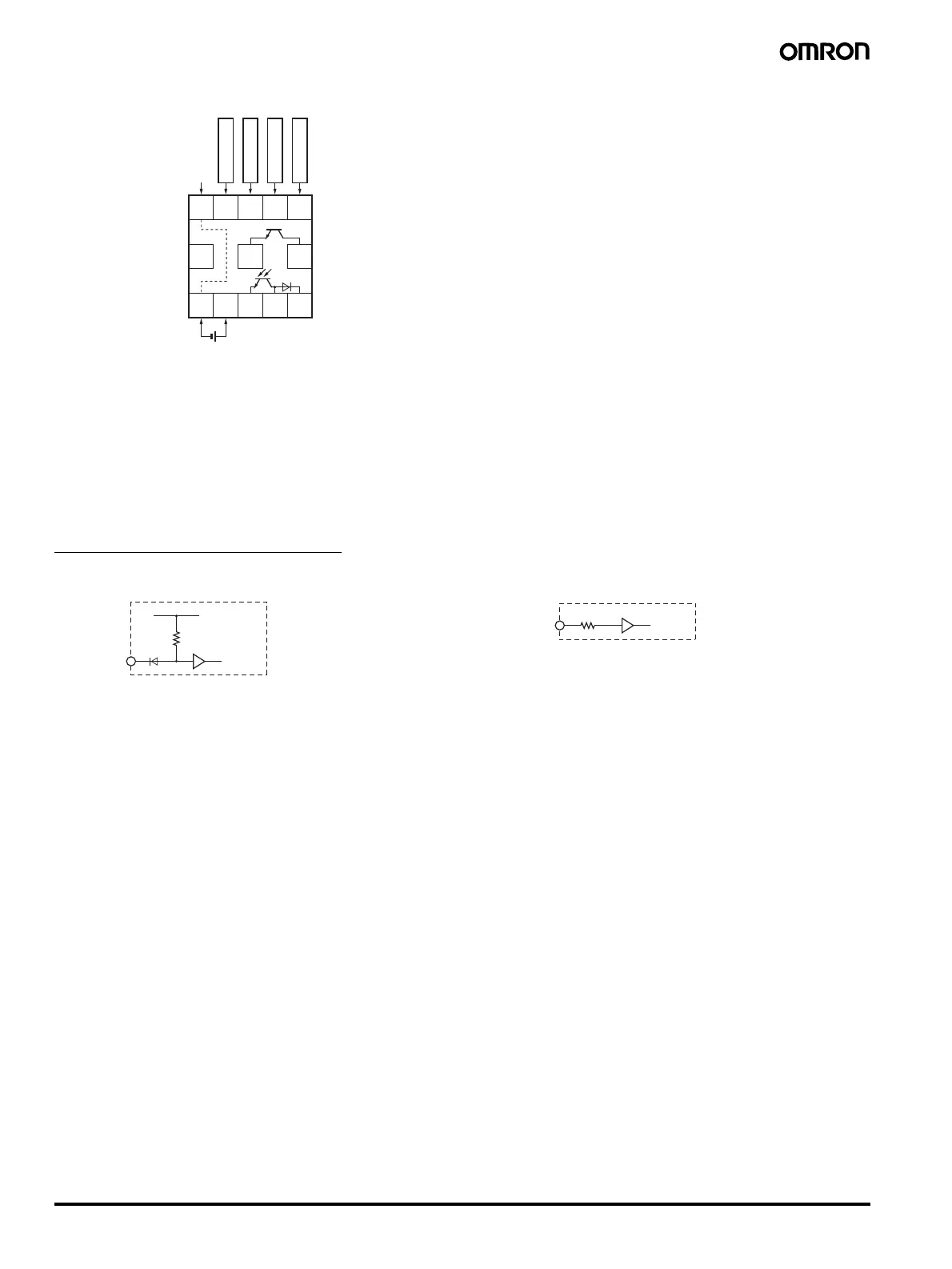
■ Terminal Arrangement
Note 1. Do not connect unused terminals as relay terminals.
2. The power supply and input circuit are not isolated.
3. Terminals 1 and 6 are connected internally.
4. Terminals 7 and 10 have the same reset function. The same function will be performed whichever terminal is connected. Terminals 7 and
10 are not connected internally, however, so do not use them for cross-over wiring.
5. Recommended lead wires: AWG18 to AWG24 (cross-sectional area: 0.205 to 0.823 mm
2
), single line or twisted-pair cable, made of copper
or aluminum.
■ Input Circuits
Signal, Reset, and Gate Input
No-voltage Input (NPN Inputs) Voltage Inputs (PNP Inputs)
678910
11 12 13 OUT1
Unused
OUT2
(+)(−)
Input use 0 V
12345
Reset
Signal
Gate
Reset
+14 V
1 kΩ
IN
Internal
circuit
Approx. 4.7 kΩ
IN
Internal
circuit
 Loading...


