EasyManua.ls Logo

Omron H5F-B - User Manual

Omron H5F-B
17 pages
Print Icon
To Next Page IconTo Next Page
Loading...
CSM_H5F_DS_E_3_3
1
Digital Daily Time Switch
H5F
Daily Time Control with Simple Operations
Specify the operation days.
(However, you can set only one pattern of operation days
and specified days.)
Up to 12 ON/OFF operations (24 for pulse-output operation).
Special holidays can be handled easily with the holiday
setting function.
Adjustments for sudden schedule changes can be made eas-
ily using output override and automatic return operation.
The operation program can be checked easily with the pro-
gram check function.
Enables pulse output operation and summer time setting.
Incorporates finger-safe terminals.
Conforms to UL, CSA, and CE marking.
Meets a variety of mounting requirements: flush mounting,
surface mounting, and DIN track mounting.
PS
E
For the most recent information on models that have been certified for
safety standards, refer to your OMRON website.
Model Number Structure
Model Number Legend
1. Mounting method
None: Flush mounting
F: Surface mounting
K: Surface mounting/track mounting
2. Language
B: English
Ordering Information
List of Models
Accessories (Order Separately)
Note: 1. Supplied with H5F-KB model.
2. Supplied with H5F-B (flush-mounting) model.
12
H5F-@B
Wiring Mounting method Model
Screw terminals Flush mounting H5F-B
Surface mounting H5F-FB
Surface mounting/track mounting H5F-KB
Name Models
Soft cover Y92A-48F1
Hard cover For H5F-B Y92A-48
For H5F-FB/-KB Y92A-48E (See note 1.)
Flush Mounting Adapter (See note 2.) Y92F-30
Mounting Track 50 cm (l) × 7.3 mm (t) PFP-50N
1 m (l) × 7.3 mm (t) PFP-100N
1 m (l) × 16 mm (t) PFP-100N2
End Plate PFP-M
Spacer PFP-S
Question and Answer IconNeed help?

Do you have a question about the Omron H5F-B and is the answer not in the manual?

Overview

The OMRON H5F Time Switch is a versatile and programmable device designed for precise control of electrical loads based on time-of-day and day-of-week schedules. It offers a range of features for flexible operation and reliable performance in various applications.

Function Description

The H5F Time Switch allows users to set ON/OFF operations for electrical loads based on daily, weekly, or holiday schedules. It supports multiple operation patterns, including pulse-output operations, and provides options for override and automatic return operations. The device features a digital quartz time base for accuracy and offers a clear display for easy monitoring and programming.

Key Functions:

  • Daily Time Control with Simple Operations: Simplifies the setup of daily ON/OFF operations, allowing for up to 12 ON/OFF operations per day.
  • Pulse-Output Operation: Enables control of loads with pulse-based requirements, with pulse widths adjustable from 1 second to 59 seconds or 1 minute to 60 minutes.
  • Partial Operation on Specified Day: Allows for different operation patterns on specific days of the week, such as holidays or weekends.
  • Holiday Setting: Enables the device to follow a specific schedule on designated holidays, overriding regular programming.
  • Override and Automatic Return Operation: Provides flexibility to temporarily override the programmed schedule, with an option for the device to automatically return to the original program after a set period.
  • Program Check Function: Allows users to review the programmed schedules to ensure accuracy before activation.
  • Time Adjustment Mode: Facilitates setting the current time and date.
  • Summer Time (DST) Function: Automatically adjusts for daylight saving time, ensuring accurate scheduling without manual intervention.
  • Switching between 12-hour (am/pm) and 24-hour Display: Offers flexibility in time display format.

Important Technical Specifications

The H5F Time Switch is designed for robust performance and compliance with international standards.

Ratings:

  • Rated Supply Voltage: 100 to 240 VAC (50/60 Hz)
  • Operating Voltage Range: 85% to 110% of rated supply voltage
  • Power Consumption: Approximately 2.4 VA at 240 VAC
  • Control Outputs:
    • Contact output: SPST-NO, 15 A at 250 VAC, resistive load; 10 A at 24 VDC, resistive load
    • Minimum applicable load: 100 mA at 5 VDC (failure level: P, reference value)
    • NEMA A300 Pilot Duty, 1/3 HP at 120 VAC
  • External Connections: Screw terminals (M3.5 screw)
  • Terminal Screw Tightening Torque: 0.98 to 1.17 N·m

Characteristics:

  • Accuracy of Operating Time: ±0.01 s/day max. (at 25°C)
  • Setting Error: ±0.05 s max. (see note 1)
  • Influence of Voltage: ±0.05 s max. (at rated voltage)
  • Influence of Temperature: ±0.05 s max. (at 25°C)
  • Time Accuracy: 115.5 per month (at 25°C)
  • Memory Protection:
    • Continuous use: 5 years min. (at 25°C)
    • Power-interruption rate of 50%: 10 years min. (at 25°C) (see note 2) (lithium battery)
  • Insulation Resistance: 100 MΩ min. (between current-carrying terminals and exposed non-current-carrying metal parts and between operating power supply circuit and control output circuits)
  • Dielectric Strength:
    • 2,000 VAC (50/60 Hz for 1 min) (between current-carrying terminals and exposed non-current-carrying metal parts and between operating power supply circuit and control output circuits)
    • 1,000 VAC (50/60 Hz for 1 min) (between non-continuous contacts)
  • Noise Immunity: 1.5 kV (between power terminals)
  • Shock Resistance:
    • Destruction: 100 m/s² 3 times each in 6 directions
    • Malfunction: 100 m/s² 3 times each in 6 directions
  • Vibration Resistance:
    • Destruction: 10 to 55 Hz with 0.375-mm single amplitude, four cycles each in three directions (8 minutes per cycle)
    • Malfunction: 10 to 55 Hz with 0.375-mm single amplitude for 10 minutes each in three directions
  • Ambient Temperature: Operating: -10 to 55°C (with no icing); Storage: -25 to 70°C (with no icing)
  • Ambient Humidity: Operating: 35% to 85%
  • Life Expectancy:
    • Mechanical (at 20°C): 100,000 operations min.
    • Electrical (at 20°C):
      • 15 A, 250 VAC, resistive load: 100,000 operations min.
      • 10 A, 250 VAC, resistive load: 50,000 operations min.
      • 10 A, 250 VAC, inductive load (cosφ = 0.7): 50,000 operations min.
      • 10 A, 24 VDC, resistive load: 50,000 operations min.
      • 300 W, 100 VAC, lamp load: 50,000 operations min.
  • Approved Safety Standards: UL60730-1, CSA E60730-1, EN60730-1 (Pollution degree 2/overvoltage category II)
  • EMC:
    • EMI (Emissions): EN61326-1 (see note 3), EN55011 Group 1 class A, EN55011 Group 1 class B
    • EMS (Immunity):
      • EN61000-4-2: 8 kV contact discharge (level 3), 15 kV air discharge (level 3)
      • EN61000-4-3: 10 V/m (Amplitude-modulated, 80 MHz to 1 GHz, 1.4 to 2 GHz) (level 3)
      • EN61000-4-4: 10 V (0.15 to 80 MHz) (according to EN61000-6-2)
      • EN61000-4-5: 2 kV line to ground (power and output lines) (level 3), 1 kV line to line (power and output lines) (level 3)
      • EN61000-4-6: 1 kV I/O signal-line (level 2)
      • EN61000-4-8: 30 A/m
      • EN61000-4-11: 10 V (0.15 to 80 MHz) (according to EN61000-6-2)
  • Case Color: Light gray (Munsell 0.7Y7/1)
  • Weight: H5F-B: approx. 165 g, H5F-KB: approx. 160 g, H5F-FB: approx. 130 g

Usage Features

The H5F Time Switch is designed for ease of use and flexibility in programming.

Operation Method:

  • Digital Quartz: Ensures high accuracy for timekeeping.
  • Time Range:
    • 24 hours × 7 days (Operation days can be specified.)
    • Up to 12 ON/OFF operations per day (Maximum 24-hour operation possible.)
    • Pulse-output operation (Pulse width can be set in units of 1 s from 1 to 59 s and in units of 1 min from 1 to 60 min.)
    • Partial operation on specified day (One or some of the operations for certain days can also be executed on other days.)
    • Forced ON/OFF operation
    • Holiday operation
    • Output override and automatic return operation
  • Display:
    • Digital display by LCD.
    • Character height: 8 mm.
    • Digital display of present time and time schedules for operation.
    • Timing chart display of present time and time schedules for operation.
  • Other Functions: Program check function, summer time function.
  • Number of Circuits: 1 independent circuit.
  • Minimum Setting Unit: 1 min.
  • Minimum Interval: 1 min.
  • Number of Operations that can be Set: 24 (see note)

Programming and Setting:

  • Mode Key: Switches between time adjustment mode, the operation setting modes, and run mode.
  • h (Hour) Key: Sets hours or switches between 12-hour (am/pm) and 24-hour display.
  • m/pWD (Minute/Pulse Time Width) Key: Sets minutes or a pulse time width.
  • WRITE Key: Writes the set data to memory or confirms settings with the program check function.
  • TEST Key: Moves the cursor to specify a day or starts the program check function.
  • SELECT Key: Specifies or cancels a specified day or switches to holiday setting mode.
  • CLR/+1h (Clear/Summer Time) Key: Erases the set data and initializes the day of operation or sets/clears summer time.
  • Output ON/OFF Switch: Turns ON the output regardless of the setting. Turns OFF the output regardless of the setting. Turns OFF the output regardless of the setting. (Override and automatic return operation can be executed by using this key in combination with the Write Key.)
  • TMR/P (Timer/Pulse output) Key: Selects timer operation or pulse-output operation.

Operating Method Examples:

  • Selecting the Mode: Easily switch between TEST, HOLIDAY, and TEST modes.
  • Time Adjustment Mode: Set the present day and time.
  • Setting Timer Operation: Program specific ON/OFF times for various days of the week.
  • Setting Pulse-output Operation: Define pulse width and duration for specific operations.
  • Setting Partial Operation on Specified Day: Customize schedules for individual days.
  • Changing Pulse-output Operation Settings: Adjust pulse settings as needed.
  • Clearing ON/OFF Settings for Individual Programs: Reset specific programs.
  • Holiday Setting: Configure holiday schedules.
  • Switching between 12-hour (am/pm) and 24-hour Display: Change time display format.
  • Override and Automatic Return Operation: Temporarily override schedules with automatic return.

Maintenance Features

The H5F Time Switch is designed for reliability and minimal maintenance, with clear guidelines for ensuring long-term performance.

Precautions for All Timers:

  • Terminal Wiring: Ensure terminals are wired correctly to prevent damage or malfunction. Do not connect more than two crimp terminals to each Time Switch terminal.
  • Power Supply:
    • Ensure the fluctuation of the supply voltage is within the permissible range.
    • Make sure that the voltage applied is within the specified range; otherwise, the internal elements of the Time Switch may be damaged.
    • Supply the power supply voltage through a breaker, relay or switch in such a way that the voltage reaches a fixed value immediately.
    • When power is turned ON, an inrush current or flow of a short-circuit current may occur. Make sure that the power supply can operate properly with a sufficient capacity and a breaker.
  • Operating Environment:
    • Avoid locations where condensation may occur due to high humidity or where temperature changes are severe.
    • Do not leave the Time Switch for long periods (e.g., one month or more) at a high temperature with output ON or in the ON state.
    • Do not operate the Time Switch in locations where strong magnetic fields, static electricity, or noise are present.
    • Do not use the Time Switch in locations exposed to dust, corrosive gases, or direct sunlight.
    • If the ambient temperature of the H5F is stored at a temperature of less than -10°C, allow the H5F to stand at room temperature for at least 4 hours before use.
    • This Time Switch is not waterproof or drip-proof. Do not use it in locations where water or oil may enter the Time Switch interior.
    • Organic solvents (such as paint thinner) as well as strong acidic or basic solutions might damage the outer casing of the H5F.
  • Installation:
    • Mounting the Time Switches side-by-side may reduce the life expectancy of the components.
    • When using heaters, be sure to use a thermal switch for the load itself.
    • When driving an inductive load (e.g., a coil), a surge voltage is generated when the contacts of a Time Switch (output) are switched, and this voltage may damage the power device connected to the Time Switch or the same line. Absorb the surge with a capacitor and resistor as shown in the wiring diagram.
  • Battery: The time and settings are backed up using a lithium battery. The display stays ON but the output turns OFF.
  • Disposal: Do not disassemble, repair, or modify the Time Switch. Doing so may result in electric shock, fire, or malfunction.

Precautions for EN61010-1 Conformance:

  • The H5F Time Switch conforms to EN61010-1, provided that the following conditions are satisfied:
    • Basic insulation is provided between the power supply and output terminals of the H5F.
    • Output terminals are connected to devices without exposed charged parts.
    • Output terminals are connected to devices with basic insulation that is suitable for the maximum operating voltage.

Others:

  • None of the Time Switch components are user-replaceable, including the battery.

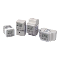
The H5F Time Switch is available in different mounting types:

  • H5F-B (Flush Mounting): Designed for flush mounting into a panel, providing a clean and integrated appearance.
  • H5F-FB (Surface Mounting): Suitable for surface mounting applications, offering easy installation on a flat surface.
  • H5F-KB (Surface/Track Mounting): Provides flexibility for both surface and DIN track mounting.

Accessories such as soft covers, hard covers, flush mounting adapters, mounting tracks, end plates, and spacers are available to facilitate installation and protection.

Omron H5F-B Specifications

General IconGeneral
BrandOmron
ModelH5F-B
CategoryTimer
LanguageEnglish

Related product manuals