H5L
11
■ Accessories (Order Separately)
Installation
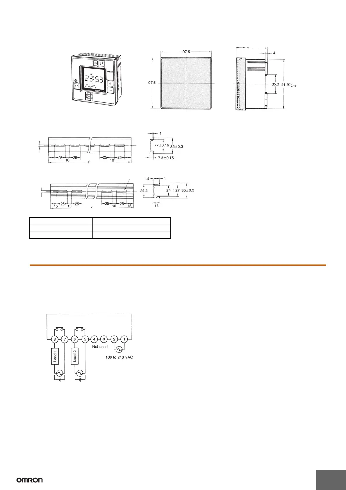
■ Connections
Connect the power supply between terminals A and B, the load for
the first circuit between terminals G and H, and the load for the
second circuit between terminals E and F. Terminals C and D are
no connects.
Front Cover
Y92A-96A
42
16
Mounting Track (Meets DIN EN 50022)
PFP-100N/PFP-50N
PFP-100N2
(See note 2)
(See note)
(See note)
Twelve,-25 × 4.5 elliptic holes (See note 2)
(See note)
Note: 1. This dimension is 15 mm on both ends in the
case of the PFP-100N but on one end in the
case of the PFP-50N.
2. The length l of each mounting track is shown
in this table.
3. A total of twelve 25 × 4.5 elliptic holes are
provided, with six holes cut from each end of
the track at a pitch of 10 mm between holes.
PFP-100N 1 m
PFP-50N 50 cm
PFP-100N2 1 m
Note: To each load, connect the power supply for load.