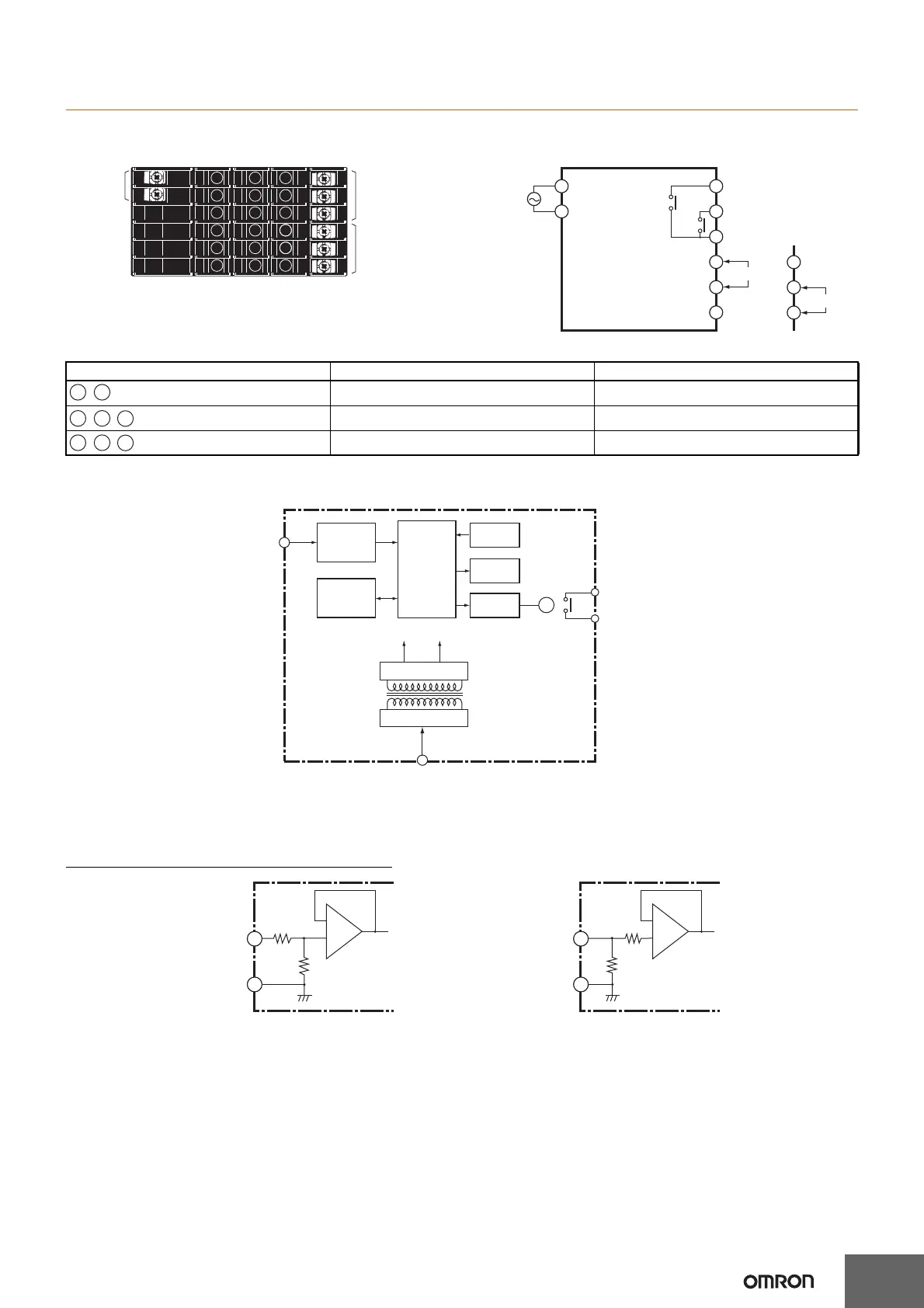
EasyManuals Logo

Omron K3MA-J Series User Manual

Omron K3MA-J Series
17 pages
To Next Page IconTo Next Page
To Previous Page IconTo Previous Page
Page #4 background imageLoading...
Page #4 background image
K3MA-J
4
Connections
Terminal Arrangement
Block Diagram
Input Circuits
Analog Input (DC Voltage/Current)
Power
supply
Output
terminals
Input
terminals
A1
A2
E1
E2
E3
E4
E5
E6
E4
E5
E6
100- to 240-VAC
type or 24-VAC/
VDC type
(No polarity for
24-VDC
connection.)
Models with
comparative
output
Voltage input
For voltage input For current input
OUT1
OUT2
COM
COM
Current input
Terminal No. Name Description
Operation power Connects the operation power supply.
Analog input Connects the voltage or current analog input.
Outputs Outputs the relay outputs.
A1 A2
-
E4 E6
,
E5
-
E1 E2
,
E3
-
X
5 V 12 V
Input Input circuit
Micro-
computer
Key
Display
Output
circuit
Contact output
(See note.)
Constant voltage circuit
Power supply circuit
EEPROM
Note: Relay output models only.
Voltage input
Current input
COM
To A/D
A+B=1 MΩ
COM
To A/D
45 Ω
4
5
6
5
A
B

Questions and Answers:

Question and Answer IconNeed help?

Do you have a question about the Omron K3MA-J Series and is the answer not in the manual?

Omron K3MA-J Series Specifications

General IconGeneral
Input TypeVoltage, Current, Thermocouple, RTD
Accuracy±0.3% FS ±1 digit
Sampling Period0.5 s
Protection structureFront panel: IP66
Control OutputVoltage
Alarm OutputRelay
MountingPanel mount
CommunicationRS-485
Relay Output250 VAC, 3 A (resistive load)
Power Supply Voltage100 to 240 VAC, 50/60 Hz; 24 VAC, 50/60 Hz; 24 VDC
Humidity35 to 85% RH (non-condensing)

Related product manuals