TECHNICAL
NOTE
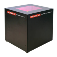
1.2 The ID-40 reader height should be adjusted so that the horizontal linear barcodes (picket fence
orientation) are typically above or below the bright reection of the reader’s illumination. The
image below shows an example in which the barcode is below the bright reection region.
MicroHAWK ID-40 Hardware Mounting
1 MicroHAWK ID-40 Hardware Mounting
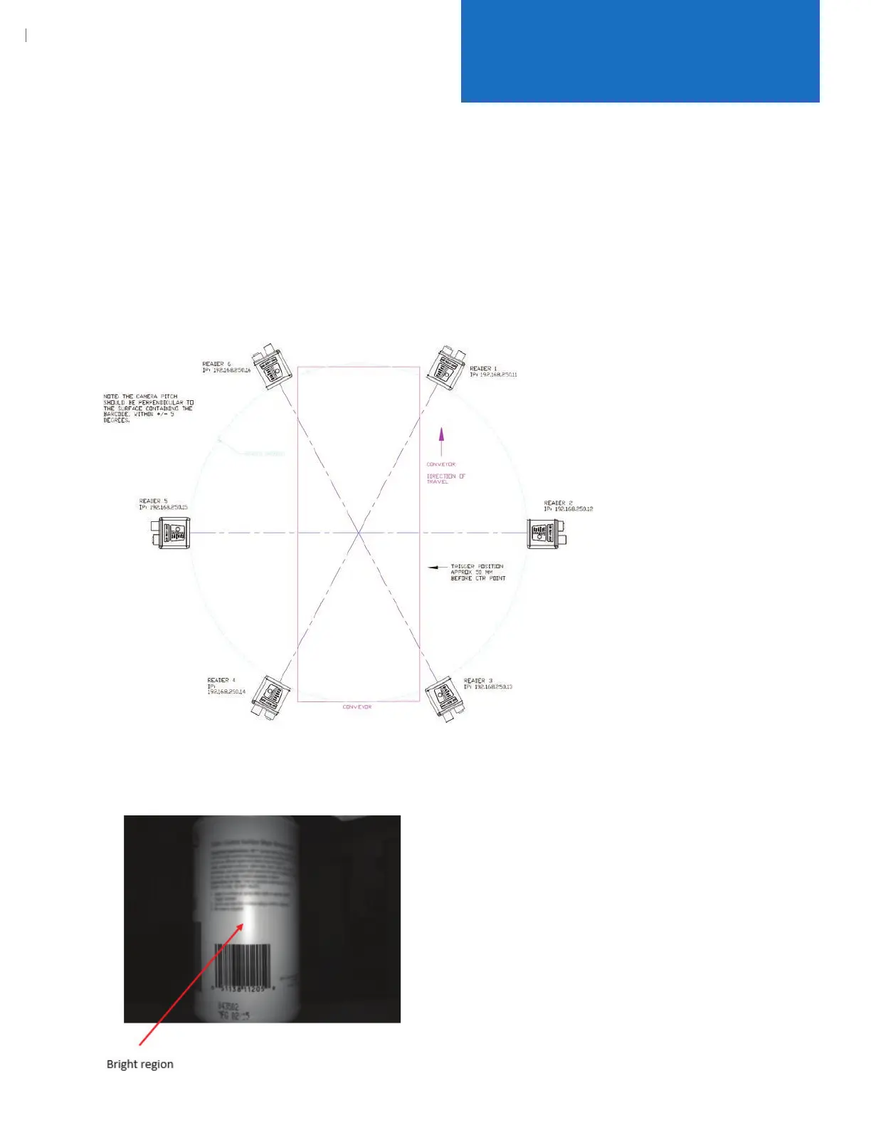
1.1 Install ID-40 readers as shown in the le “ID-40 360 read cam placement.dwg”. The basic layout is shown
below. The cameras are mounted 245 mm from the center point of the code read position. The
camera pitch (angle) should be perpendicular to the surface containing the barcode, within
+/- 5 degrees.
NOTE: The installer will need to determine the best trigger position based on the type of product to be
read on the conveyor. The current trigger position is based on a 67 mm diameter cylindrical object.
MicroHAWK ID-40 Setup
Technical Note: MicroHAWK ID-40 360
º
Barcode Reading Solution