2 Installing the NB Unit and Connecting Peripheral Devices
2-34
NB-series Programmable Terminals Setup Manual(V107)
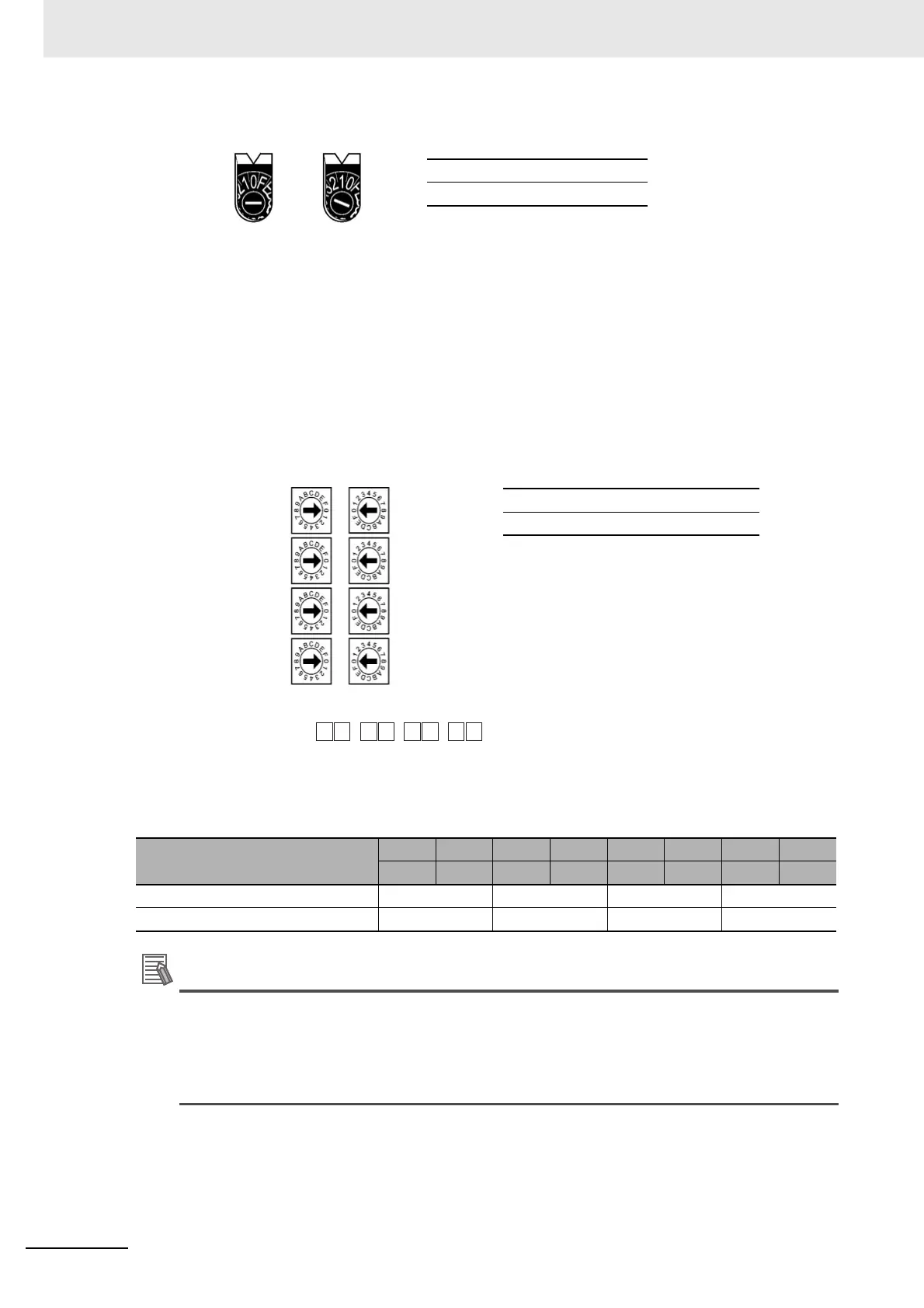
Setting Node Numbers
Set the upper digit using the left rotary switch and the lower digit using the right rotary switch.
The factory setting is 01. The Node ID of the dip switch here must be consistent with that of PLC in
the “Network Device Setting” dialog box for the actual project created in the NB-Designer.
Setting the Rear Panel Switches
Setting Local IP Addresses
Set the local IP address for the Ethernet Unit using the eight hexadecimal rotary switches (local IP
address setting switches), expressing each 4-bit value as a single hexadecimal digit. Set the IP
address as a hexadecimal using the eight switches combining SW1 and SW2, SW3 and SW4, SW5
and SW6, and SW7 and SW8, as shown in the following diagram.
Example: Setting 130.58.17.32 (Decimal)
This address will be 82.3A.11.20 in hexadecimal, so the switch would be set as shown in the
following table.
Additional Information
• When converting the data by “automatic generation” method (default method), please set
the node numbers to be consistent with the values of local IP address setting switches SW7
and SW8, and set ID thresholds for other Hosts to 0. If the Host ID value corresponding to
the IP address is not consistent with the node number, the ERC indicator will flash.
• Please use the CX-Programmer to set the subnet mask for the CPU Bus Unit Setup Area.
Switch Setting
SW1 SW2 SW3 SW4 SW5 SW6 SW7 SW8
8 2 3 A 1 1 2 0
Local IP address in hexadecimal 82 3A 11 20
Local IP address in decimal 130 58 17 32
NODE
NO.
×16
1
×16
0
Setting range
01 to FE (1 to 254 decimal)
Local IP address
SW1
SW2
SW3
SW4
SW No.
SW8
SW7
SW6
SW5
1
2 3 4 5 6 7 8
...
Setting range for each switch
0 to F
WWW.NNC.IR
 Loading...


