3-47
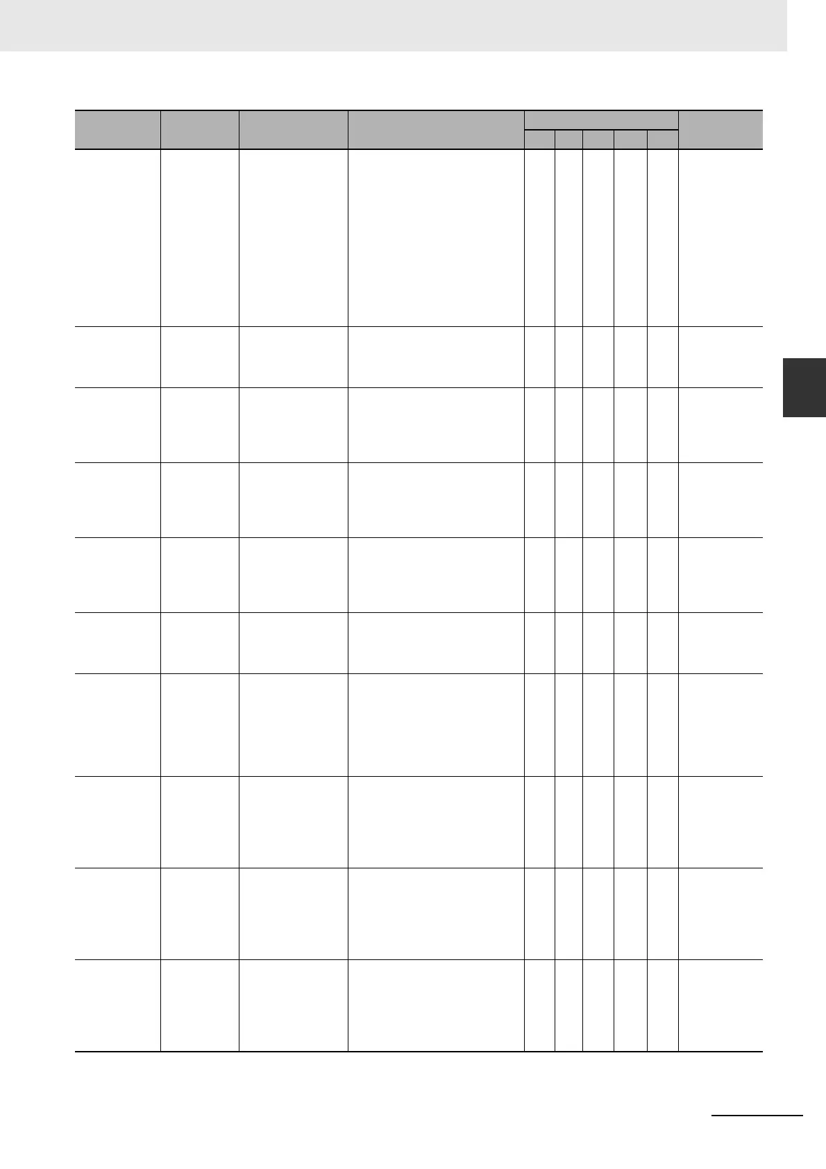
3 Error Tables
NJ-series Troubleshooting Manual (W503)
3-1 Errors by Source
3
3-1-3 Errors in the Motion Control Function Module
54770000 hex Cam Table
Data Error
during Cam
Motion
The phases are not
in ascending order
in the cam table.
• Data containing cam table
phases that are not in ascend-
ing order was detected during
cam motion.
• The phase and displacement of
the start point in the cam table
were not 0 during cam opera-
tion.
• The phase of the end point in
the cam table when converted
to pulses was not 1 pulse or
greater during cam operation.
S NJ-series
CPU Unit
Motion Con-
trol User’s
Manual (Cat.
No. W507)
54850000 hex Immediate
Stop Instruc-
tion Executed
An Immediate Stop
(MC_ImmediateSto
p) instruction was
executed.
• An Immediate Stop instruction
was executed.
S Same as
above.
54860000 hex Axes Group
Immediate
Stop Instruc-
tion Executed
An Axes Group
Immediate Stop
(MC_GroupImmedi
ateStop) instruc-
tion was executed.
• A Group Immediate Stop
instruction was executed.
S Same as
above.
64450000 hex Positive Soft-
ware Limit
Exceeded
The position
exceeded the posi-
tive software limit
while the axis is in
motion.
• The position exceeded the posi-
tive software limit.
S Same as
above.
64460000 hex Negative
Software
Limit
Exceeded
The position
exceeded the nega-
tive software limit
while the axis is in
motion.
• The position exceeded the neg-
ative software limit.
S Same as
above.
64470000 hex In-position
Check Time
Exceeded
The in-position
check was not com-
pleted within the
monitoring time.
• Time is required to complete
positioning.
S Same as
above.
64480000 hex Following
Error Limit
Exceeded
The error between
the command cur-
rent position and
actual current value
exceeded the Fol-
lowing Error Over
Limit Value.
• The positioning operation has
poor following performance and
the actual motion is slower than
the command.
S Same as
above.
64490000 hex Immediate
Stop Input
The immediate stop
input turned ON.
•
An immediate stop input signal
w
as detected.
• The immedia
te stop input signal
is not connected correctly or
the logic setting for the immedi-
ate stop input is wrong.
S Same as
above.
644A0000 hex Positive Limit
Input
Detected
The positive limit
input turned ON.
• A positive limit input signal was
detected.
• The positive limit input signal is
not connected correctly or the
logic setting for the positive limit
input is wrong.
S Same as
above.
644B0000 hex Negative
Limit Input
Detected
The negative limit
input turned ON.
• A negative limit input signal was
detected.
• The negative limit input signal is
not connected correctly or the
logic setting for the negative
limit input is wrong.
S Same as
above.
Event code Event name Meaning Assumed cause
Level
Reference
Maj Prt Min Obs Info

 Loading...


