Cat. No.
Model numbers and manual name
Machine Automation Controller NX-series
EtherCAT Coupler Units User’s Manual
Safety Network Controller
NX-series Safety Control Unit/
Communication Control Unit
User’s Manual
Machine Automation Controller NX-series
System Units User’s Manual
Machine Automation Controller NX-series
Data Reference Manual
W519
Z395
W523
W525
NX-ECC201
NX-PD/PF/PC
NX-TBX
NX-SL5
NX-SID/SIH
NX-SOD/SOH
NX-CSG
NX Series
Related Manuals
Machine Automation Controller NX-series
Safety Control Units User’s Manual
Z930
NX-SL
NX-SID
/NX-SIH
NX-SOD
/NX-SOH
Machine Automation Controller NX-series
Safety Control Units Instructions Reference
Manual
Z931
NX-SL
NX-SID
/NX-SIH
NX-SOD
/NX-SOH
Sysmac Studio Version 1 Operation Manual W504
SYSMACSE2
Although the Safety Control Units are used for machine safety
applications, the required level of safety may not be achieved
depending on how the Safety Control Units are used. Observe
the warnings that are provided in the following parts of the
Warnings section in the NX-series Safety Control Unit User’s
Manual: 1) Setting Up a Risk Assessment System, 2) Protective
Measure, 3) Role of Safety Products, 4) Installing Safety
Products, 5) Observing Laws and Regulations, 6) Observing
Usage Precautions, and 7) Transferring Devices and
Equipment.
Omron Companies shall not be responsible for conformity with
any standards, codes or regulations which apply to the
combination of the Product in the Buyer’s application or use of
the Product. At Buyer’s request, Omron will provide applicable
third party certification documents identifying ratings and
limitations of use which apply to the Product. This information
by itself is not sufficient for a complete determination of the
suitability of the Product in combination with the end product,
machine, system, or other application or use. Buyer shall be
solely responsible for determining appropriateness of the
particular Product with respect to Buyer’s application, product or
system. Buyer shall take application responsibility in all cases.
NEVER USE THE PRODUCT FOR AN APPLICATION
INVOLVING SERIOUS RISK TO LIFE OR PROPERTY OR IN
LARGE QUANTITIES WITHOUT ENSURING THAT THE
SYSTEM AS A WHOLE HAS BEEN DESIGNED TO ADDRESS
THE RISKS, AND THAT THE OMRON PRODUCT(S) IS
PROPERLY RATED AND INSTALLED FOR THE INTENDED
USE WITHIN THE OVERALL EQUIPMENT OR SYSTEM.
Also refer to the manuals for all of the Units that you will use.
Suitability for Use
Regional Headquarters
OMRON EUROPE B.V.
(Importer in EU)
Wegalaan 67-69, 2132 JD Hoofddorp
The Netherlands
Tel: (31)2356-81-300
Fax: (31)2356-81-388
OMRON ASIA PACIFIC PTE. LTD.
438B Alexandra Road, #08-01/02
Alexandra Technopark,
Singapore 119968
Tel: (65) 6835-3011
Fax: (65) 6835-2711
OMRON ELECTRONICS LLC
2895 Greenspoint Parkway, Suite 200
Hoffman Estates, IL 60169 U.S.A.
Tel: (1) 847-843-7900
Fax: (1) 847-843-7787
OMRON (CHINA) CO., LTD.
Room 2211, Bank of China Tower,
200 Yin Cheng Zhong Road,
Pu Dong New Area, Shanghai,
200120, China
Tel: (86) 21-5037-2222
Fax: (86) 21-5037-2200
Note: Specifications subject to change without notice.
OMRON Corporation
Industrial Automation Company
Contact: www.ia.omron.com
Shiokoji Horikawa, Shimogyo-ku, Kyoto, 600-8530 JAPAN
Tel:(81)75-344-7093 / Fax:(81)75-344-8197
(Manufacturer)
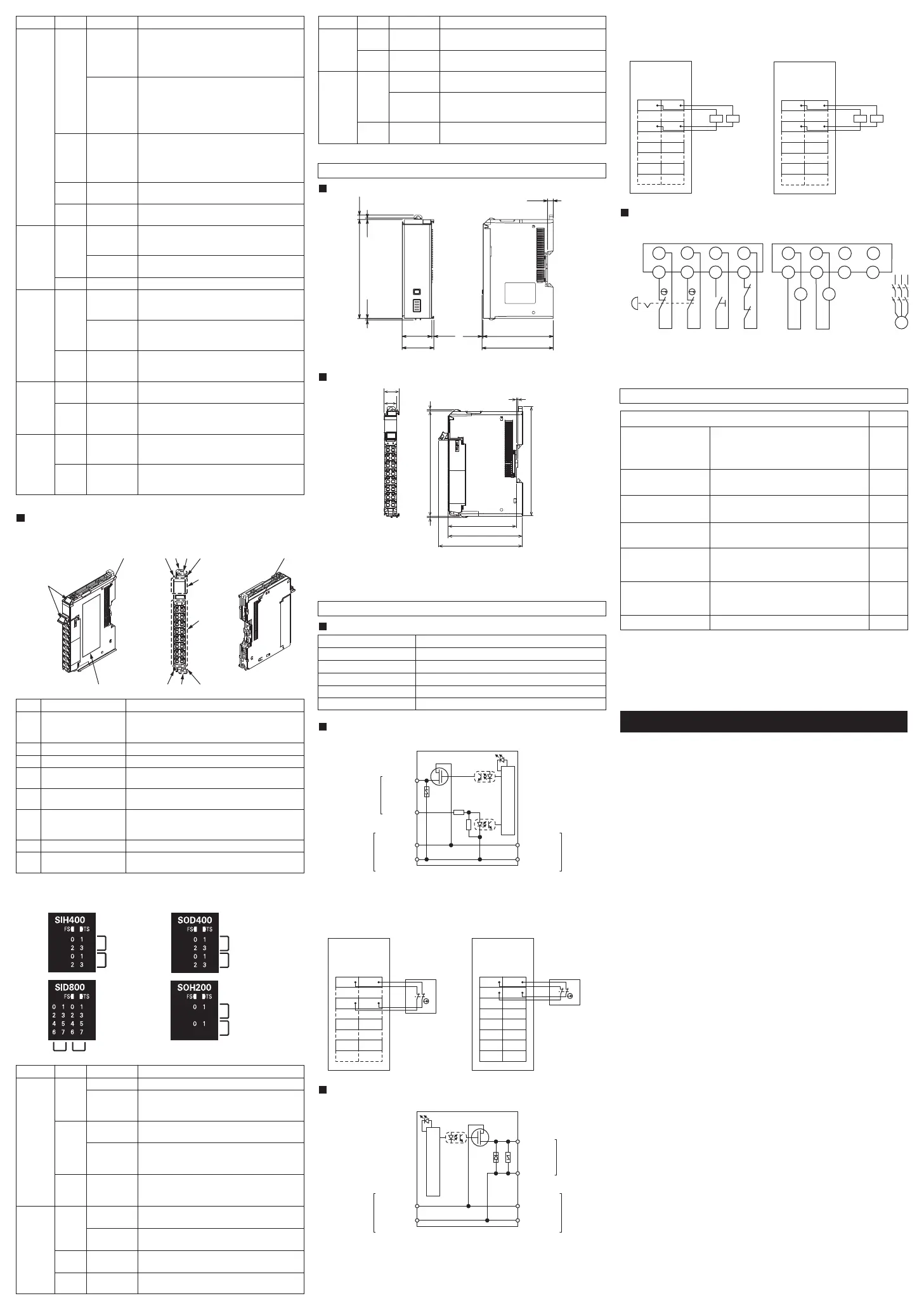
(1) Internal Circuits
(2) Terminal Connection Diagram and Wiring Example
Dimensions
Internal Circuits and Wiring
Color
Indicator
Status
Green
FS
(FSoE
Status)
Lit.
[For NX-SL3
00] All FSoE connections are
established and there are no errors in any
Safety CPU Unit functions.
[For NX-SL5
00] All FSoE connections are
established.
Flashing (at
1-s intervals)
Red
[For NX-SL3
00] One or more FSoE
connections are not established or are
currently being established and there are no
errors in any Safety CPU Unit functions.
[For NX-SL5
00] The FSoE connections are
being established.
Flashing (at
1-s intervals)
Green/
Red
[For NX-SL3
00] An FSoE communications error,
program execution error, or other minor error that
is attributed to the safety application has occurred.
[For NX-SL5
00] An FSoE communications
error occurred.
Alternates at
1-s intervals.
―
[For NX-SL3
00] The safety application data
has not been stored.
Not lit.
Power is not being supplied, FSoE communications
are not executed or a fatal fault has occurred.
RedP ERR
*1
Lit
The safety program, CIP Safety communications,
and FSoE communications stopped due to the
running program or settings, which resulted in error.
Flashing (at
1-s intervals)
―
Local error occurred in the running program.
Not lit No errors in the running program or settings
Green
RUN Lit. Execution of a safety program is in progress
(operation is in progress in RUN mode, or
DEBUG mode (RUN)).
Flashing (at
1-s intervals)
―
Initialization is in progress (from when the
power supply is turned ON until RUN or
PROGRAM mode is entered).
Not lit. Operation is in progress in PROGRAM mode
or DEBUG mode (STOPPED), or a fatal fault
has occurred.
Yellow
DEBUG Lit.
―
Operation is in progress in DEBUG mode. (the
debug function can be executed)
Not lit. Operation is in progress in a mode other than
DEBUG mode or a fatal fault has occurred.
(the debug function cannot be executed)
Yellow
VALID Lit.
―
Safety application data from the execution of
the safety validation is stored in the
non-volatile memory.
Not lit.
Safety application data from the execution of the
safety validation is not stored in the non-volatile
memory, or a fatal fault has occurred.
Color
Indicator
Description
Status
YellowIN/OUT Lit
―
Safety input/output terminal is ON and there
are no errors.
Not lit Safety input/output terminal is OFF or an error
has occurred.
RedIN/OUT
ERR
―
Lit
Flashing (at
1-s intervals)
An error has occurred in the safety input/output
terminal for the other channel of the dual
channel I/O.
Not lit
An error has occurred in the safety input/output
terminal.
There are no errors in the safety input/output
terminal.
Description
*1. NS and P ERR are not provided for NX-SL3300/SL3500.
*1. Si4 to Si7 are not provided for NX-SIH400.
*1. So2 to So3 are not provided for NX-SOH200.
*1. The dimension is 1.35 mm for Units with lot numbers through December 2014.
*2. The dimension from the attachment surface of the DIN Track to the front surface
of the Safety I/O Unit.
IOG
Terminals
I/O power supply 0 V
NC
Not used (Do not connect)
Si0 - Si7
Input terminals
So0 - So3 Output terminals
T0 - T1 Test output terminals
Function
NX-SIH400
NX-SID800
(2) Terminal Connection Diagram and Wiring Example
NX-SOH200
NX-SOD400
(2) I/O Indicators
NX-SIH400/SID800/SOH200/SOD400
The following section describes the specifications of each indicator.
(A) Marker attachment
location
Letter
Name
The locations where markers are attached. The markers
made by OMRON are installed for the factory setting.
Commercially available markers can also be installed.
(B) NX bus connector This is the NX-series bus connector.
(C) Unit hookup guides
These guides are used to connect two Units.
(E) Protrusions for
removing the Unit
The protrusions to hold when removing the Unit.
(F)
Indicators
The indicators show the current operating status of the
Safety Input/Output Unit or the signal input/output status.
Refer to (2) I/O Indicators.
(G) Terminal block
The terminal block is used to connect external devices.
(H) Unit specifications The specifications of the Safety Input/Output Unit
are given here.
(D) DIN Track mounting
hooks
These hooks are used to mount the NX Unit to a
DIN Track.
Function
*1. The bottom switches are not provided for NX-SL3300/SL3500.
Si0 to Si3: Safety input terminals
T0, T1: Test output terminals
Si0 to Si7: Safety input terminals
T0, T1: Test output terminals
So0 to So1: Safety output terminals
IOG: I/O power supply 0 V
So0 to So3: Safety output terminals
IOG: I/O power supply 0 V
Unit: mm
Unit: mm
Unit 2 (NX-SIH400) Unit 3 (NX-SOD400)
The appearance of the NX-series Safety Input/Output Unit is shown below. Please
check the names and functions of each part.
Safety Input/Output Unit
(C)(D)
(H)
(G)
(F)
(C)
(A)
(E)
(C)(E)
(C)
(B)
(B)
NX-SL3300/SL3500/SL5500/SL5700
100
(2.1)
1.1 71
5.8
(72.1)
30
32.1
4.5
1.51.5
*1
NX-SIH400/SID800, NX-SOH200/SOD400
80
71
104.5
100
14.1
65.2
*2
12.0
1.5 1.5
0.55
*1
Terminal Markings
(1) Internal Circuits
Safety Input Unit
Internal Circuits
T0 - 1
Terminal block
Si0 - 7
*1
I/O power
supply +
I/O power
supply -
NX bus
connector
(left)
I/O power
supply +
I/O power
supply -
NX bus
connector
(right)
Safety Output Unit
Internal Circuits
So0 - 3
*1
Terminal block
IOG
I/O power
supply +
I/O power
supply -
NX bus
connector
(left)
I/O power
supply +
I/O power
supply -
NX bus
connector
(right)
I/O Wiring Example: Emergency Stop (Dual Channel) with Manual
Reset
S1: Emergency stop pushbutton
S2: Reset switch
KM1, KM2: Contactors
M: Motor
KM1 KM2
M
KM1
KM2
KM1
KM2
S1
S2
Si0 Si1 Si2 Si3
T0 T1 T0
T1
So0 So1 So2 So3
IOG IOG IOG IOG
Color
Indicator
GreenTS
The Unit is operating normally.
Red
Status
Lit
Initialization is in progress, or I/O allocation
information data is being downloaded from the
Sysmac Studio.
Flashing (at
1-s intervals)
―
An NX bus communications error, I/O allocation
information data error, or other recoverable minor
error that is attributed to the NX bus has occurred.
Not lit • There is no Unit power supply
• The Unit is restarting
• Waiting for initialization to start
GreenFS
(FSoE
Status)
Lit
The FSoE connections are established and there
are no errors in any Safety I/O Units functions.
Flashing (at
1-s intervals)
Red
The FSoE connections are being established.
Flashing (at
1-s intervals)
―
An FSoE communications error, safety input/output
terminal error, or other minor error has occurred.
Not lit Power is not being supplied or a fatal fault has
occurred.
Flashing (at
2-s intervals)
Lit A hardware error, WDT error, or other critical
error has occurred.
Description
(1) Part Names
Si0
Safety Input Unit
NX-SID800
Safety Switch
A1 B1
A8 B8
Si1
T0 T1
Si2 Si3
T0 T1
Si4 Si5
T0 T1
Si6 Si7
T0 T1
So0
Safety Output Unit
NX-SOH200
A1 B1
A8 B8
So1
L L
IOG IOG
NC NC
NC NC
So0
Safety Output Unit
NX-SOD400
A1 B1
A8 B8
So1
L L
IOG IOG
So2 So3
IOG IOG
Si0
Safety Input Unit
NX-SIH400
A1 B1
A8 B8
Si1
T0 T1
Si2 Si3
T0 T1
Safety Switch
IN
IN ERR
IN
IN ERR
OUT
OUT ERR
OUT
OUT ERR

 Loading...


