9-27
9-5 Interface Monitor Settings
OMNUC G5-series AC Servomotors and Servo Drives User’s Manual (with Built-in EtherCAT Communications)
9
Details on Servo Parameter Objects
In the same way as for Analog Monitor 1, analog signals of various monitors can be output from
the analog monitor connector on the front panel.
Refer to the Analog Monitor 1 Selection (3416 hex) for the method to set this object.
Set the output gain for analog monitor 2.
Refer to the Analog Monitor 1 Scale Setting (3417 hex) for the method to set this object.
Select the analog monitor output voltage direction.
These are the output voltage range and the output direction when the Analog Monitor 1 Selection
or Analog Monitor 2 Selection is set to the Feedback Motor Speed, and the Analog Monitor 1 Scale
Setting or the Analog Monitor 2 Scale Setting is set to 0 (i.e., 1V = 500 r/min).
3418 hex
Analog Monitor 2 Selection
Setting
range
0 to 21 Unit −
Default
setting
4
Data
attribute
A
Size 2 bytes (INT16) Access RW PDO map Not possible.
All
3419 hex
Analog Monitor 2 Scale Setting
Setting
range
0 to 214748364 Unit
Monitor unit of 3418
hex/V
Default
setting
0
Data
attribute
A
Size 4 bytes (INT32) Access RW PDO map Not possible.
All
3421 hex
Analog Monitor Output Selection
Setting
range
0 to 2 Unit −
Default
setting
0
Data
attribute
A
Size 2 bytes (INT16) Access RW PDO map Not possible.
All
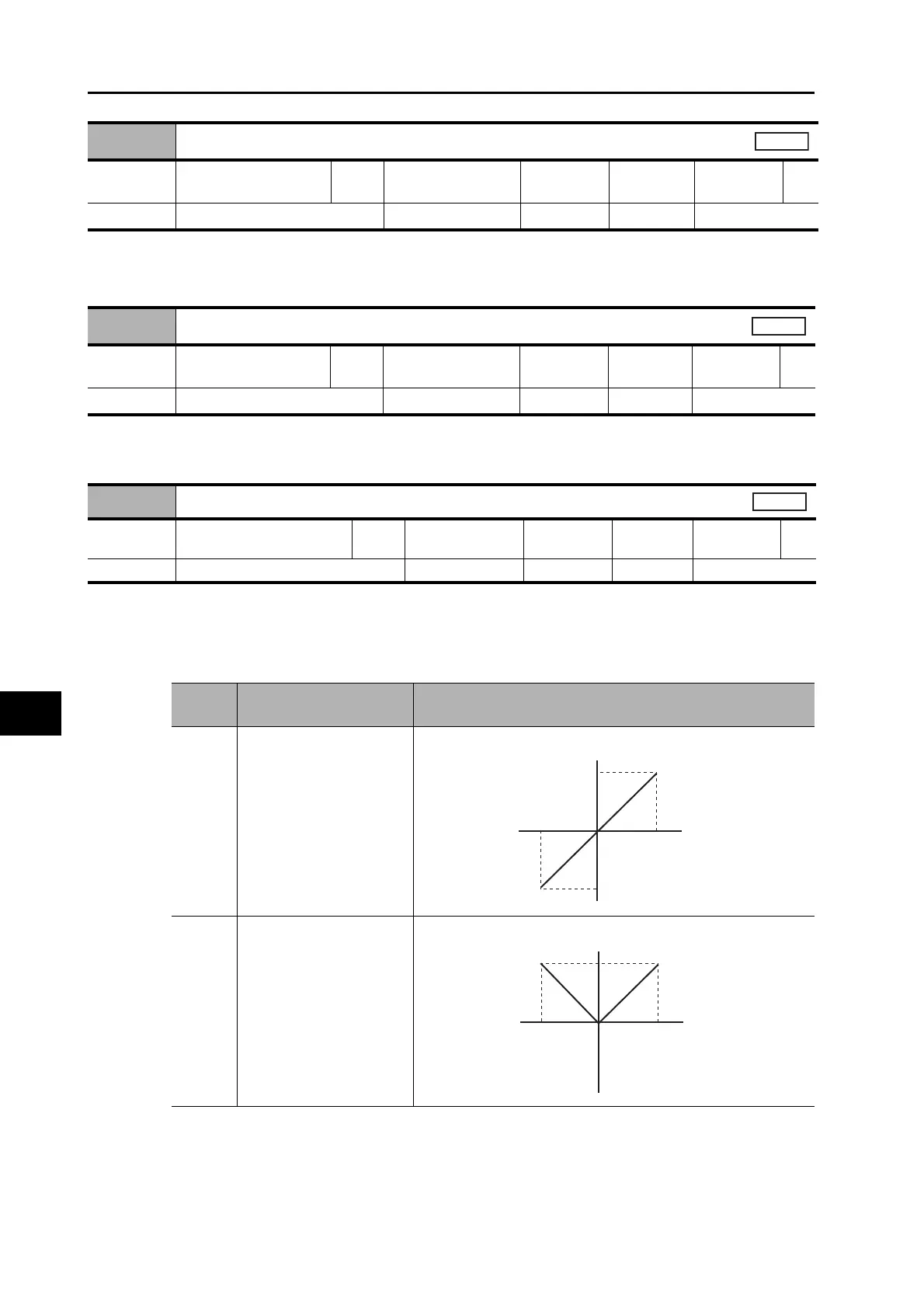
Set
value
Output range Data output
0 −10 to 10 V
1 0 to 10 V
10 V
-10 V
0 V
-5,000 5,000 [r/min]
Feedback
Motor
Speed
Output voltage [V]
10 V
-10 V
0 V
-5,000 5,000 [r/min]
Feedback
Motor
Speed
Output voltage [V]
 Loading...
