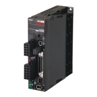
Do you have a question about the Omron R88D-KT50F and is the answer not in the manual?
Details warranty terms, limitations of liability, and other contractual agreements for product use.
Outlines critical safety information, display conventions, and specific precautions for safe and correct product operation.
Lists general specifications, characteristics, connector specifications, and I/O circuits for Servo Drives across various models and input voltages.
Details general specifications, characteristics, brake specifications, and torque-rotation speed characteristics for OMNUC G5-series Servomotors.
Explains installation requirements for Servo Drives and Servomotors, covering space conditions, environment, impact, and load considerations.
Provides wiring diagrams and connection examples for peripheral equipment, main circuits, and motor connections.
Details wiring methods and component selection criteria to ensure conformance with EMC directives for noise immunity.
Explains the outline of operation for position control, parameters requiring settings, and related functions like electronic gear.
Details the outline of operation for speed control, parameters requiring settings, and related functions like acceleration/deceleration.
Explains the outline of operation for torque control, parameters requiring settings, and related functions like speed limit input.
Details the outline of operation for fully-closed control, setting procedures, and parameters related to external encoders.
Explains the STO function for cutting off motor current and stopping the motor via safety equipment signals, including precautions.
Explains fundamental parameters like Rotation Direction Switching, Control Mode Selection, and Realtime Autotuning Mode Selection.
Details parameters for adjusting position, speed, and torque loop gains, including integral time constants and filter settings.
Explains parameters for adaptive filters and notch filters used to suppress resonance and vibration in the mechanical system.
Details essential pre-operation checks, including power supply voltage, terminal block wiring, motor, encoder, and I/O connector connections.
Outlines procedures for trial operation in different control modes (position, speed, torque, fully-closed) to confirm system correctness.
Explains the purpose of gain adjustment, methods including realtime autotuning and manual tuning, and provides adjustment examples.
Details the realtime autotuning process for estimating load inertia and automatically setting optimal gains, including precautions.
Guides users on performing manual tuning for position, speed, and torque control modes, including parameter adjustments and application examples.
Provides preliminary checks for problems, precautions, and procedures for replacing Servomotors or Servo Drives.
Provides a comprehensive list of alarm codes, error detection functions, probable causes, and recommended measures for troubleshooting.
Explains how to diagnose errors using alarm displays and operation status, and provides troubleshooting measures for common issues.
| Type | Servo Drive |
|---|---|
| Model | R88D-KT50F |
| Output Power | 5.0 kW |
| Applicable Motor Capacity | 5.0 kW |
| Input Voltage | 3-phase 200 to 240 V AC |
| Supply Voltage | 200 to 240 V AC |
| Main Circuit Power Supply | 200 to 240 V AC, 50/60 Hz |
| Control Circuit Power Supply | 200 to 240 V AC |
| Control Method | Sine-wave PWM control |
| Protection Functions | Overvoltage, Undervoltage, Overload |
| Ambient Temperature | 0°C to 55°C |
| Storage Temperature | -20 to 85°C (with no icing or condensation) |
| Ambient Humidity | 90% RH or less (non-condensing) |
| Vibration Resistance | 4.9 m/s² |


