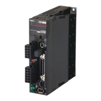
Do you have a question about the Omron OMNUC G5 R88D-KT50F and is the answer not in the manual?
Details Omron's exclusive warranty for products, disclaiming all other warranties, express or implied.
States that Omron makes no warranty or representation, express or implied, about non-infringement, merchantability, or fitness for a particular purpose.
Outlines Omron's obligation to replace, repair, or repay/credit for non-complying products under specific conditions.
Excludes liability for special, indirect, incidental, or consequential damages and limits liability to the product's individual price.
Specifies the warranty period and scope, excluding certain failures like improper handling or natural disasters.
Disclaims responsibility for special, indirect, or passive damages and for programming outcomes.
Requires customers to check standards, regulations, and compatibility for product applications.
Provides instructions on what to do and what not to do to ensure safe product usage.
Provides instructions on what to do and what not to do to ensure proper operation and performance.
Lists applicable EC Directives and UL/cUL standards for the OMNUC G5-series.
Lists the standard models available for Servo Drives, Servomotors, and their combinations.
Provides detailed external and mounting dimensions for Servo Drives and Servomotors.
Details general specifications, characteristics, and connector information for Servo Drives.
Provides general specifications, characteristics, and encoder specifications for Servomotors.
Covers space, mounting, and environmental conditions for installing Servo Drives and Servomotors.
Explains wiring methods, including peripheral equipment connections and main circuit wiring.
Details wiring requirements for compliance with EMC directives for noise immunity.
Explains how Servo Drives absorb regenerative energy and methods for calculation.
Explains position control operation, parameters, and block diagrams using pulse train input.
Details speed control operation, parameters, and block diagrams using analog voltage input.
Explains torque control operation, parameters, and block diagrams using analog voltage.
Describes motor speed control using preset speeds via digital I/O signals.
Details fully-closed control using an external encoder for precise positioning.
Explains the damping control function to reduce vibration in mechanical units.
Explains the STO function used to cut off motor current via safety inputs.
Details parameters for adjusting position loop gain, speed loop gain, and filters.
Explains the purpose, methods, and procedure for adjusting servo system gains.
Details the realtime autotuning function for estimating load inertia and setting optimal gains.
Provides a list of alarm codes, detection functions, probable causes, and measures.
Explains how to diagnose errors using alarm displays and operation status, and take measures.
| Type | Servo Drive |
|---|---|
| Series | OMNUC G5 |
| Model Number | R88D-KT50F |
| Rated Output Current | 5.0 A |
| Input Frequency | 50/60 Hz |
| Ambient Operating Temperature | 0 to 55°C |
| Storage Temperature | -20 to 85°C |
| Applicable Motor Capacity | 0.05 kW |
| Control Method | Sine-wave PWM |
| Communication | MECHATROLINK-II |
| Protection Functions | Overvoltage, Undervoltage, Overheat, Encoder Error |
| Vibration Resistance | 4.9 m/s² |
| Power Supply Voltage | Single-phase/Three-phase 200 to 240 VAC |
| Ambient Humidity | 35 to 85% (with no condensation) |


