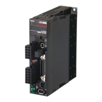
Do you have a question about the Omron R88D-KT20F and is the answer not in the manual?
Details Omron's warranty terms, limitations of liability, and buyer's remedies for product defects.
Omron Companies are not liable for special, indirect, incidental, or consequential damages.
Details the warranty period and scope, excluding specific failures like improper use or natural disasters.
Omron assumes no responsibility for special, indirect, or passive damages arising from the product.
Customer must check standards, regulations, and compatibility for combined products.
Read this section and main text before use for required safety information and precautions.
Explains the display of precautions in the manual and their meanings, including DANGER, WARNING, and CAUTION.
Provides guidelines for safe product use, including installing covers and shields, and handling stored products.
Lists specific DANGER warnings related to flammable materials, installation on non-flammable surfaces, system configuration, cable usage, power supplies, and wet hands.
Lists specific CAUTION warnings regarding specified combinations, locations for storage/installation, and hot components.
Lists CAUTION warnings related to installation and wiring, such as not stepping on the drive, blocking openings, mounting direction, clearances, impact, wiring, tightening screws, terminal types, power supply voltage, safety measures, shielding, stop relays, and battery polarity.
Lists CAUTION warnings for safe operation and adjustment, including test operations, parameter settings, motor separation, alarm handling, brake usage, load inertia, safety devices, power supply interruptions, and frequent power cycling.
Lists CAUTION warnings for maintenance and inspection, such as data transfer after replacement, disassembly prohibition, and power supply turn-off for prolonged periods.
Presents detailed external and mounting dimensions for Servo Drives, Servomotors, and regeneration resistors.
Provides general specifications, characteristics, and connector details for OMNUC G5-series Servo Drives.
Lists general specifications, characteristics, and encoder specifications for OMNUC G5-series Servomotors.
Explains basic parameters like Rotation Direction Switching, Control Mode Selection, and Realtime Autotuning Mode Selection.
Details parameters for Position Loop Gain, Speed Loop Gain, and their related time constants and switching modes.
Explains parameters for Adaptive Filter, Notch Filters, and Damping Control for suppressing vibration.
Details parameters for analog speed and torque command inputs, including scaling, offset, and direction settings.
Explains parameters for setting analog monitor outputs, input selections, and excessive input levels.
Covers extended parameters like Drive Prohibition Input Selection, Stop Selection, and Overload/Overspeed Detection Levels.
Details special parameters such as Feed-forward settings, Inertia Ratio, and Vibration Suppression parameters.
Provides a step-by-step guide for operating the motor and drive after installation and wiring.
Details the procedure for performing trial operation in Position, Speed, Torque, and Fully-closed Control Modes.
Provides preliminary checks and precautions for troubleshooting problems.
Provides a comprehensive list of alarm codes, error detection functions, probable causes, and measures.
Details error diagnosis using alarm displays and operation status, offering appropriate measures for each error.
Explains the importance of periodic inspection and replacement of components for long-term operation.
| Type | Servo Drive |
|---|---|
| Model | R88D-KT20F |
| Output Current | 20 A |
| Applicable Motor Capacity | 2.0 kW |
| Communication | MECHATROLINK-II |
| Ambient Operating Temperature | 0 to 55 °C |
| Power Supply Voltage | 200 to 240 VAC |
| Control Method | Position Control, Speed Control, Torque Control |
| Protection Functions | Overvoltage, Overheating |
| Series | R88D Series |
| Ambient Operating Humidity | 20 to 90 % |


