2 Power Supply Technical Information
Glossary
Note. As a general rule, the ambient temperature is measured at 50 mm from the Power Supply.
● Input Voltage
The input voltage is the input voltage and corresponding
frequency range at which the rated operations and performance
can be maintained. The AC input voltages shown are effective
values. An input voltage of 100 VAC is input when the input
voltage selector terminals are shorted with a short bar and an
input voltage 200 VAC is input when these terminals are open.
Main applicable models: S82K (90 W, 100 W),
S82J (300 W, 600 W)
Note. Models equipped with 100/200 VAC selection are delivered set to 200-
VAC input. Therefore, be sure to thoroughly check the input voltage
selector terminals before use. Using the incorrect voltage, whether 200
VAC or 100 VAC, will cause the Power Supply to malfunction.
● Input Current
Standard Switch-mode Power Supplies rectify AC input current.
Usually, rectification is achieved using capacitor inputs and a
smoothing capacitor through which a reactive current is allowed
to flow. Therefore, the input current depends on the output
power, input voltage, power factor, and efficiency, as follows:
The power factor of a Switch-mode Power Supply is usually
between 0.4 and 0.6. For details on efficiency, refer to the
information in the datasheet for each model.
Item Description Details
Efficiency (%)
The output power divided by the effective input power. The higher the effi-
ciency, the smaller the internal power loss of the Power Supply.
---
Input
condition
Voltage range
The voltage applied to the AC input terminals. The voltage fluctuation range
is indicated in parentheses.
---
Frequency The frequency of the voltage applied to the AC input terminals. ---
Current
The current value flowing to the AC input terminals. This value is the station-
ary current and will fluctuate depending on the load.
Refer to Input Current on page 2.
Power factor The effective input power divided by apparent power ---
Harmonic current
The harmonic current component excluding the fundamental wave included
in the current waveform.
Refer to Harmonic Current Suppression on
page 8.
Leakage current
The current leaking to the ground from the input lines through the casing of
the Power Supply.
Refer to Leakage Current on page 3.
Inrush current The peak current that flows when the input is turned ON. Refer to Inrush Current on page 3.
Output
character-
istics
Voltage adjustment range
The range in which the output voltage can be adjusted using the Output
Voltage Adjuster (V.ADJ).
Refer to Voltage Adjustment Range on
page 3.
Ripple noise voltage
The compound value of the ripple that appears between the output termi-
nals and high-frequency noise. This value is expressed as a peak to peak
(p-p).
Refer to Ripple and Noise on page 3.
Input variation influence
The variation in the output voltage when the input voltage gradually varies
within the input voltage fluctuation range.
Refer to Input Variation Influence on page
4.
Load variation influence
(rated input voltage)
The variation influence in the output voltage when the output current gradu-
ally varies within the specified load range.
Refer to Load Variation Influence on page
4.
Startup time
The time from when the input voltage is turned ON until the output voltage
reaches 90% of the rated output voltage.
---
Output hold time
The time after the input voltage is shut off during which the output voltage
maintains the constant-voltage precision range.
---
Functions
Overload protection
Prevents damage to the Power Supply if the output current exceeds the
rated current (including output short-circuits).
Refer to Overcurrent Protection on page 4.
Overvoltage protection Detects excessive voltage between output terminals and turns OFF outputs. Refer to Overvoltage Protection on page 5.
Parallel operation Increases capacity through parallel connection of multiple Power Supplies. Refer to Parallel Operation on page 6.
Serial operation
Increases output voltage through serial connection of multiple Power Sup-
plies.
Refer to Series Operation on page 7.
Other
Ambient operating
temperature
The allowable range for the ambient temperature in which continued opera-
tion is possible. The ambient temperature is the temperature not affected by
the heat generated by the Power Supply itself. (See note.)
Refer to Precautions Common to all Power
Supplies on CD.
Storage temperature
The allowable range for the ambient temperature in which performance will
not deteriorate due to long-term storage. The Power Supply itself is in a
non-operational state.
Refer to Precautions Common to all Power
Supplies on CD.
Ambient operating
humidity
The allowable ambient humidity range in which the product can be used
continuously.
Refer to Precautions Common to all Power
Supplies on CD.
Dielectric strength
Test for confirming the insulation strength by applying a specified voltage
between two specified points for a specified length of time.
Refer to Dielectric Strength on page 4.
Insulation resistance
DC resistance indicating insulation characteristics between two specified
points.
Refer to Insulation Resistance Test on page
4.
Vibration resistance The vibration resistance characteristics. ---
Shock resistance The shock resistance characteristics. ---
Conducted emission Noise voltage that is generated in the Power Supply’s AC input terminals. ---
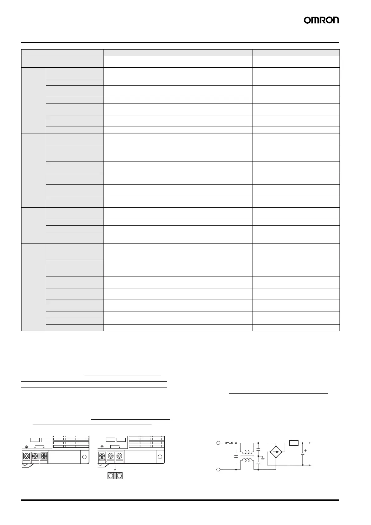
100 V 200 V
678
SHORT
100-120V
VOLTAGE SELECT
OPEN
200-240V
Terminals short-circuited
usin
the short bar.
678
SHORT
100-120V
VOLTAGE SELECT
OPEN
200-240V
Short bar removed and
terminals open.
Input current =
Output voltage
Input voltage × Power factor × Efficiency
Input Rectifier/Smoothing Circuit
Input fuse
Inrush current protection circuit
Input
smoothing
capacitor
 Loading...