©All Rights Reserved
OMRON Corporation
3116647-5A (Side-B)
EN
Contact address
OMRON ELECTRONICS LLC
Phone: 1-800-55-OMRON
Phone: 1-847-843-7900
Fax : 1-847-843-7787
OMRON CANADA INC.
Phone: 1-416-286-6465
Phone: 1-866-986-6766
Fax : 1-416-286-6648
UNITED KINGDOM
OMRON ELECTRONICS LTD.
Phone: 44-1908-258-258
Fax : 44-1908-258-158
1
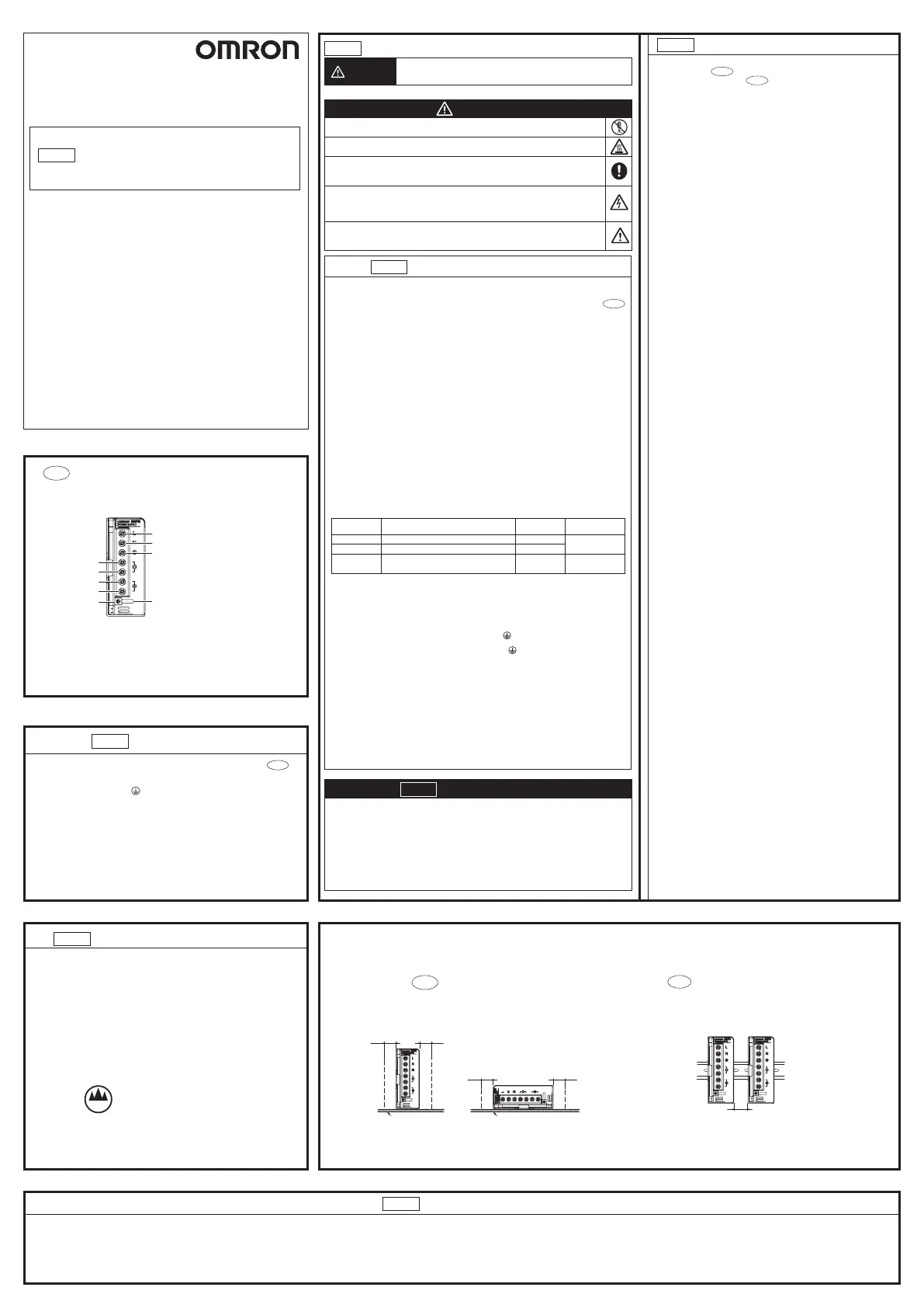
Fig.
Nomenclature
Fig.1
Safety standards
EN
①
Overvoltage category II.
: Complies with GB4943-2011.
②
Use in pollution degree2 environment.
: Complies with GB4943-2011.
③
Conformance to GB4943.1-2011 standards for ambient temperature.
35℃(S8FS-G150□□□)
④
(S8FS-G150□□□)series power supply could be used in information technology
products.
: Complies with GB4943-2011.
≤2000m
⑤Only for safe use below 2000 meters altitude.
: Complies with GB4943-2011.
OMRON Corporation
Shiokoji Horikawa, Shimogyo-ku, kyoto, 600-8530 Japan
OMRON Europe B.V.
Wegalaan 67-69, 2132 JD Hoofddorp, The Netherlands
S8FS-G
SWITCHING
POWER SUPPLY
MODEL
INSTRUCTION MANUAL
EN
Thank you for purchasing the S8FS-G.
This Instruction Manual describes the functions, performance, and
application methods required to use the S8FS-G.
• Make sure that a specialist with electric knowledge operates the S8FS-G.
• Read and understand this Instruction Manual, and use the product with
enough understanding.
Keep this Instruction Manual close at hand and use it for reference during operation.
⑧
⑦
④
⑤
⑨
⑥
②
③
①
This diagram show the S8FS-G150C
S8FS-G150
Nomenclature
EN
① and ②
Input terminals (L), (N)
(The fuse is located on the (L) side.)
③ Protective earthing terminal (
)
(This is the protective earthing terminal
specified in the safety standards. Always
ground this terminal.)
④, ⑤, ⑥ and ⑦
DC output terminals (–V), (+V)
⑧ Output indicator (DC ON: green)
⑨ Output voltage adjuster
EN
Key to Warning Symbols
Fig.2
Precautions for Safe Use
EN
CAUTION
CAUTION
• Warning Symbols
Suitability for Use
EN
Omron Companies shall not be responsible for conformity with any standards, codes or regulations which
apply to the combination of the Product in the Buyer’ s application or use of the Product. At Buyer’ s
request, Omron will provide applicable third party certification documents identifying ratings and limitations
of use which apply to the Product. This information by itself is not sufficient for a complete determination of
the suitability of the Product in combination with the end product, machine, system, or other application or
use. Buyer shall be solely responsible for determining appropriateness of the particular Product with
respect to Buyer’ s application, product or system. Buyer shall take application responsibility in all cases.
NEVER USE THE PRODUCT FOR AN APPLICATION INVOLVING SERIOUS RISK TO LIFE OR
PROPERTY OR IN LARGE QUANTITIES WITHOUT ENSURING THAT THE SYSTEM AS A WHOLE HAS
BEEN DESIGNED TO ADDRESS THE RISKS, AND THAT THE OMRON PRODUCT(S) IS PROPERLY
RATED AND INSTALLED FOR THE INTENDED USE WITHIN THE OVERALL EQUIPMENT OR SYSTEM.
Indicates a potentially hazardous situation which, if not avoided,
may result in minor or moderate injury or in property damage.
• Minor electric shock, fire, or Product failure may occasionally occur. Do not
disassemble, modify, or repair the Product or touch the interior of the Product.
• Minor electric shock, fire, or Product failure may occasionally occur. Do not
allow any pieces of metal or conductors or any clippings or cuttings resulting
from installation work to enter the Product.
(1) Installation and Storage Environment
1. Store the Product at a temperature of −25 to 75°C and a humidity of 90% or less.
2. Take adequate measures to ensure proper heat dissipation to increase the
long-term reliability of the Product.
The S8FS-G150 are cooled by natural convection.
Mount them so that air convection will occur around them.
3. The internal parts may occasionally deteriorate or be damaged. Do not use the
Product beyond the derating curve range.
4. Refer to the Product catalog for the derating curve for each mounting direction.
5. Use the Product at a humidity of 90% or less.
6. Avoid places where the Product is subjected to direct sunlight.
7. Avoid places where the Product is subjected to penetration of liquid, foreign
substance, or corrosive gas.
8. Avoid places subject to shock or vibration.
A device such as a contact breaker may be avibration source. Set the Power
Supply as far as possible from possible sources of shock or vibration.
9. If the Power Supply is used in an area with excessive electronic noise, be sure to
separate the Power Supply as far as possible from the noise sources.
10. The internal parts may occasionally deteriorate and be broken due to adverse heat
radiation. Do not loosen the screws on the Power Supply.
(2) Installation and Wiring
1.
Connect the ground completely. A protective earthing terminal stipulated in safety standards
is used. Electric shock or malfunction may occur if the ground is not connected completely.
2. The light ignition may possibly be caused. Ensure that input and output terminals
are wired correctly.
3. Use the following wiring material to prevent smoking or ignition of wiring material
caused by abnormal loads.
Notes:
1. The current rating per terminal of the output terminals is shown below. If the current exceeds the rating
on a terminal, always use two terminals simultaneously.
• S8FS-G150 : 20 A
2. After completing the wiring, create the following clearance and creepage distance between the terminal
wires and metal case.
Between any two of wires connected to the L, N and FG ( ) terminals and between wires connected
to L, N terminals and the metal case: 6.4mm min.
Between any two of wires connected to the +V, -V and FG ( ) terminals and between wires
connected to +V, -V terminals and the metal case: 3.2mm min.
4. Do not apply more than 150 N force to the terminal block when tightening it to avoid
the terminal block damaged.
5. Be sure to remove the sheet covering the product for machining before power-on.
(3) Output Voltage Adjustment
1. The output voltage adjuster (V.ADJ) may possibly be damaged. Do not add
unnecessary power.
2.
Do not exceed the rated output capacity and current after adjusting the output voltage.
(4) Refer to the other Instructions Manual (3114994-5) for details on the optional models
(S8FS-GE, S8FS-G-R, and S8FS-G-W).
(5) Refer to the product datasheet for details.
• Minor injury due to electric shock may occasionally occur. Do not touch the
terminals while power is being supplied. Always close the terminal cover after
wiring. Working voltage can be 370 V max. inside. This voltage can be also
available 30s after the switch off.
• Minor fires may occasionally occur. Tighten terminal screws to the specified
torque (M3.5 screws: 6.55 to 10.00 lb-in (0.74 to 1.13 N•m), M4 screws: 9.56
to 11.68 lb-in (1.08 to 1.32 N•m)).
• Minor burns may occasionally occur. Do not touch the Product while power is
being supplied or immediately after power is turned OFF.
Terminal Model Torque
Recommended
wire type
Input
6.55 to 10.00 lb-in
(0.74 to 1.13 N•m)
Output
Protective earthing
terminal
AWG12 to 16
AWG12 to 14
S8FS-G150
S8FS-G150
AWG12 to 16
6.55 to 10.00 lb-in
(0.74 to 1.13 N•m)
S8FS-G150
Precautions for Correct Use
EN
Fig.3
Fig.2
■
Mounting
Standard mounting
Standard Mounting on DIN Rail
S8FS-GCD
• When the screw holes provided on the chassis are used, the screws must not
protrude more than 3 mm
inside the Power Supply. If you must use screws that are longer than given above,
refer to the product datasheet.
Tighten the mounting screws to the following torque:
M3 screws: 0.48 to 0.59 N·m
M4 screws: 1.08 to 1.32 N·m
• Metal plate is strongly recommended as the mounting panel.
■
Input Voltage Tolerance
Rating: 100 to 240 VAC
• Mains supply tolerance for AC input: -10 to +10% (90 to 264 VAC)
■Parallel Operation
This Power Supply is not designed for parallel operation. If you attempt parallel
operation, overheating may damage internal parts.
Parallel operation is possible with the optional models (S8FS-G60024-W).
■
Output Voltage Adjustment
Default Setting: Set at the rated voltage
Adjustable Range: Adjustable with "V.ADJ "
⑨
on the front surface of the product
from –10% to +15% of the rated output voltage.
Turning clockwise increases the output voltage, and turning counterclockwise
decreases the output voltage.
Note:
The output voltage may increase beyond the voltage adjustment range +15% or
more when the V.ADJ adjuster ⑨ is used.
When adjusting the output voltage, check the output voltage of the Power Supply
and be sure that the load is not destroyed.
■
Dielectric Strength Test
Rated dielectric strength:
3,000 VAC between < input terminals ① ② together > and < output terminals ④ ⑤ ⑥
⑦
together > for 1 minute.
When testing, set the cutoff current for the withstand voltage
test device to 20 mA.
Notes:
1. If a tester switch is used to apply or cut off 3,000 V suddenly, the resulting
impulse voltage may occasionally damage the Product.
2. When performing the test, be sure to short-circuit all the output terminals to
protect them from damage.
■
Insulation Resistance Test
When testing the insulation resistance of the Power Supply, use a DC ohmmeter
at 500 VDC.
Note:
When performing the test, be sure to short-circuit all the output terminals to protect
them from damage.
■
Overload Protection
The load and the Product are automatically protected from overcurrent damage
by the overload
protection function. When the current returns to within the rated range, the Product
will automatically return to normal operation.
Notes:
1. Internal parts may possibly deteriorate or be damaged if a short-circuited,
overload, or boost load state continues during operation.
2. Internal parts may possibly deteriorate or be damaged if the Product is used for
applications with frequent inrush current or overloading at the load end. Do not
use the Product for such applications.
■
Overvoltage Protection
This Product automatically protects itself and the load from overvoltage.
Overvoltage protection is activated if the output voltage rises above approx.
120% of the rated output voltage. To reset the Product, leave the Product off for
more than 3 minutes and then turn it on again.
Note:
Be sure to clear the cause of the overvoltage, before turning on the Product.
■
Conformance to EU Directives
Refer to the catalogue and this instruction manual for details on the operating
condition for EMC-compliance.
If you use the S8FS-G150 at 80% or more of the rated load, the harmonics
standard will not be met. Do not connect the Product to a public power source when
you operate it at 80% or more of the rated load.
S8FS-G150
20 mm min.
20 mm min.
20 mm min.
20 mm min.
∗ ∗
Fig. 2 Standard mounting
Fig. 3
Standard mounting (DIN rail)
20 mm min.

 Loading...