Do you have a question about the Omron S8VK-G Series and is the answer not in the manual?
Lists S8VS parts being discontinued and their recommended replacements.
Lists datasheets for S8VS and S8VK series.
Visual examples of the S8VS power supplies being discontinued.
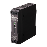
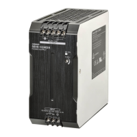
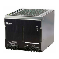
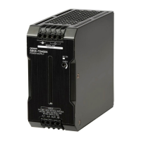
Visual examples of the S8VK replacement power supplies.
Wiring diagrams for discontinued S8VS power supplies.
Wiring diagrams for recommended S8VK-G replacement power supplies.
Explains the function of each numbered terminal in the diagrams.
Guidelines and diagrams for mounting S8VS and S8VK-G units.
Detailed procedure for mounting on DIN rails.
Detailed dimension drawings for S8VS models.
Detailed dimension drawings for S8VK-G models.
Detailed technical specifications for S8VS series.
Detailed technical specifications for S8VK-G series.
Details on EMI compliance and safety standards.
Graphs showing load ratio vs. ambient temperature for derating.
Explains overload and overvoltage protection functions.
Highlights of the S8VK-G series operation and installation.
Lists safety standards and compliance for the S8VK-G series.
Explanation of how S8VK-G model numbers are built.
List of available S8VK-G models and their parameters.
Detailed input/output parameters for S8VK-G models.
Information on Power Boost, protection, timing, and EMI.
Internal circuit diagrams for various S8VK-G power ratings.
Identifies and explains the parts and terminals of S8VK-G models.
Derating curves and operating data for S8VK-G series.
Mounting options and the Power Boost function.
Details on overload, overvoltage, and timing characteristics.
Information on undervoltage alarms and other indications.
Dimension drawings for S8VS models with screw terminals.
Dimension drawings for S8VS models with screwless terminals.
Specifications for DIN rail mounting rails and covers.
Details on available mounting brackets for S8VS.
Essential warnings for safe use and handling of S8VS.
Guidelines for correct and safe wiring connections.
Explains self-diagnostics, error codes, and alarm functions.
Details on maintenance forecast and total run time monitors.
Explains capacitor deterioration and operational principles.
Detailed input/output parameters for 15W to 180W S8VS models.
Detailed input/output parameters for 240W and 480W S8VS models.
Internal circuit diagrams for S8VS 15W, 30W, and 60W models.
Internal circuit diagrams for S8VS 90W, 120W, 180W, and 240W models.
Internal circuit diagram for S8VS 480W and alarm output connections.
Identifies parts and terminals for S8VS 15W and 30W models.
Identifies parts and terminals for S8VS 60W to 180W models.
Identifies parts and terminals for S8VS 240W and 480W models.
Derating curves for various S8VS models and conditions.
Mounting methods, overload, and peak current protection.
Timing characteristics and undervoltage alarm indication.
Dimension drawings for S8VS models with screw terminals.
Dimension drawings for S8VS models with screwless terminals.
Specifications for DIN rail mounting rails and covers.
Details on available mounting brackets for S8VS.
How to change modes and interpret operation displays.
Peak hold reset, undervoltage, and multiple alarm indications.
Explanation of self-diagnostics and error code meanings.
Details on maintenance forecast and total run time monitors.
Essential warnings for safe use and handling of S8VS.
Best practices for wiring, installation environment, and operating life.
Series operation, positive/negative outputs, and backup operation.
General terms, pricing, warranties, and liability limitations.
Advice on product suitability, performance, and specification changes.
| Output Voltage | 24 VDC |
|---|---|
| Input Voltage | 100-240 VAC |
| Output Power | 480 W |
| Operating Temperature | -10 to +60 °C |
| Protection Features | Overvoltage |
| Mounting Type | DIN Rail |
| Safety Standards | UL 508 |
| Dimensions (W x H x D) | 22.5 x 90 x 100 mm |