2
F3SJ-B-01TS
Quick Installation Manual
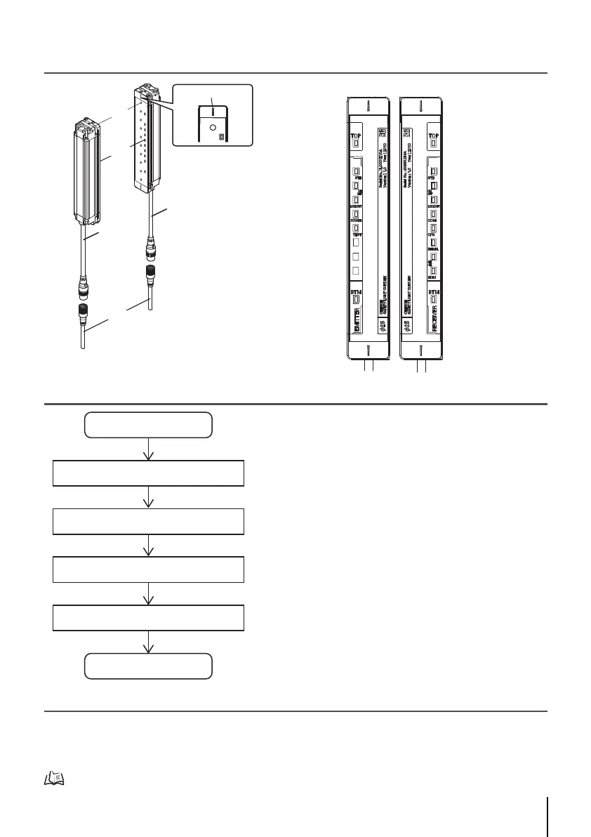
2. System Components
3. Light Curtain Setup Flow
4. Function Selection Flow Chart
Wiring depends on the function to be used. Shown below are the available functions.
- External Test Function
- External Device Monitoring Function
- Auxiliary Output Function
For details, refer to F3SJ-B-01TS series user's manual.
Receiver
10. Bottom-beam-state indicator (Blue)
6. Test indicator (Green)
5. Power indicator (Green)
4. Lockout indicator (Red)
3. ON/OFF-state indicator (Green/Red)
2. Stable-state indicator (Green)
1. Top-beam-state indicator (Blue)
4. Lockout indicator (Red)
3. ON/OFF-state indicator (Green/Red)
2. Stable-state indicator (Green)
1. Top-beam-state indicator (Blue)
10. Bottom-beam-state indicator (Blue)
9. External device monitoring indicator (Green)
8. Not used
7. Internal error indicator (Red)
6. Configuration indicator (Green)
5. Communication indicator (Green)
Emitter
Emitter
Receiver
Connection cable
(Black)
Indicator
Beam
Extension cable
Connection
cable (Gray)
Beam center-line mark
Setup
Function Selection
Wiring
Mounting/Beam Alignment
Pre-Operation Checklists/Maintenance Checklists
Done
. . . .page 2
. . . .page 3
. . . .page 4
. . . .page 10

 Loading...