3
F3SJ-B-01TS
Quick Installation Manual
5.Wiring Examples
For wiring examples of input/output circuit and other wiring examples than below, refer to F3SJ-B-01TS series user's manual.
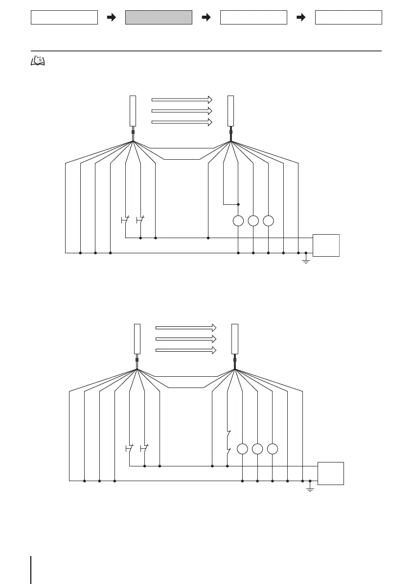
5-1. EDM not used, auto reset mode, external test used
5-2. EDM used, auto reset mode, external test used
24 V (Brown)
External device monitoring input (Red)
0 V (Blue)
Auxiliary
output (Yellow)
Safety output 1 (Black)
Safety output 2 (White)
Shield
S1
S2
KM1, KM2
K1
: External test switch (connect to 24 V if a switch is not required)
: Lockout reset switch (connect to 24 V if a switch is not required)
: Safety relay with force-guided contact (G7SA) or magnetic contactor
: Load or PLC, etc. (for monitoring)
Shield
Not Used (Red)
0 V (Blue)
Not Used (White)
Test input (Black)
Reset input (Yellow)
24 V (Brown)
S1 S2
K1 KM1 KM2
0 V
Emitter
Receiver
(Gray) Communication line (+)
(Pink)
Communication line (-)
Power
supply
+24 VDC
F39-JDA-L F39-JDA-D
*1 *1
*2
*1 Use a switch for micro loads (Input specifications: 24V, 1.0mA or less)
*2 F3SJ can work even if K1 is not connected.
S1
S2
KM1, KM2
K1
: External test switch (connect to 24 V if a switch is not required)
: Lockout reset switch (connect to 24 V if a switch is not required)
: Safety relay with force-guided contact (G7SA) or magnetic contactor
: Load or PLC, etc. (for monitoring)
24 V (Brown)
External device monitoring input (Red)
0 V (Blue)
Auxiliary output (Yellow)
Safety output 1 (Black)
Safety output 2 (White)
Shield
Shield
Not Used (Red)
0 V(Blue)
Not Used (White)
Test input (Black)
Reset input (Yellow)
24V (Brown)
KM1
KM2
S1
*1 *1
*2
S2
K1 KM1 KM2
0 V
Emitter
Receiver
(Gray) Communication line (+)
(Pink)
Communication line (-)
Power
supply
+24 VDC
F39-JDA-L F39-JDA-D
*1 Use a switch for micro loads (Input specifications: 24V, 1.0mA or less)
*2 F3SJ can work even if K1 is not connected.
Mounting/Beam Alignment
Wiring
Function Selection
Pre-Operation Checklist /
Maintenance Checklists

 Loading...